
________________________________________________________________________________
Massey Ferguson 8240, 8260 gearbox dynashift with power shuttle - Removing and install
Uncouple the Massey Ferguson 8240, 8260 tractor between the engine and the gearbox.
Drain the gearbox. Remove the selector cover. Remove the clutch cover plate, hydraulic control unit and front clutch from the power. Remove the input unit.
Place the housing in vertical position and split the power shuttle rear
clutch from the input unit.
Removing and disassembling the cover, front
clutch casing and brake
Using two locally made lugs or rings, remove the shaft (7), cover (13)
and casing (21) assembly.
recover both the stop (70) and the locating pin.
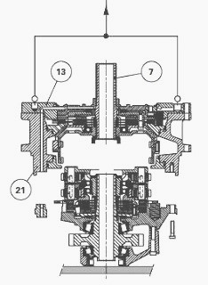
Remove the piston (37) from the casing (21). Scrap the O’rings (35)
(36).
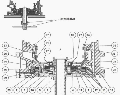
Place the cover and casing assembly vertically on a workbench in which a
hole (O approximately 65 mm) has been drilled in order to accommodate
the
transmission shaft.
Immobilize the MF 8240, 8260 transmission shaft (7) and a locally made
spindle. Remove the screws (33) and split the secondary ring gear (34)
from the
secondary ring gear carrier (1).
Remove the circlip (69), pressing on the center of the primary ring gear
(31) in order to compress the spring washer (77). Remove the primary
ring gear (31) and
ball bearing (27). Recover the spring washer.
Hold the transmission shaft (7) and remove the screws (25). Take out the
secondary ring gear carrier (1).
Remove the casing (21) along with the piston (22). Remove the piston and
scrap the O’rings (24)(26).
Remove the discs (3) (15), intermediate plates (2), clutch plate (17),
hub (5), springs (20) and the thrust plate (16).
Extract the Belleville washer (4), clutch housing (14) and transmission
shaft (7) taking care to draw them towards the inside face of the cover
(13) and recover the
friction washer (10).
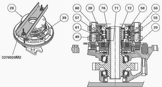
Removing and splitting the planet carrier unit
Removal
Compress the planet carrier assembly.
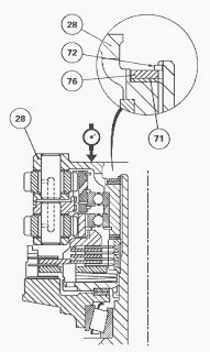
Remove the retaining ring (72). Remove the stud washer (76), planet
carrier assembly and the shims
(71) mounted along the mating faces of the primary planet carrier (28).
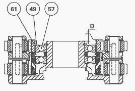
Remove the secondary sun gear (61) and the retaining ring (49) (if
necessary).
Remove the circlip (55). Remove the bearing (57) and the spacer (56).
Split the secondary planet carrier (39) from the primary planet carrier
(28).
Remove the retaining ring (60) and bearing (58).
Place the secondary planet carrier in vertical position.
Remove the
needles (63) by hitting the planet carrier gently against a wooden shim.
Split the planet carrier
from the primary sun gear (64) along with the retaining ring (62) and
oil splasher (75).
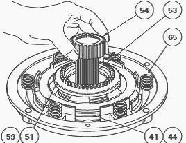
Remove the MF 8260, 8240 clutch plate (38), springs (65) and discs (41) (the latter should be separated from the clutch plate (44)). Remove the rear clutch housing assembly (59), thrust plate (45) and the last disc (41).
Remove the friction washer (51).
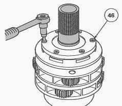
Remove the screws (46). Remove the cover (47) and the Belleville washers
(52). Separate the thrust plate (45), discs (50) and intermediate plates
(48).
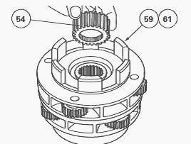
Remove the hub (54).
Assembling the planet carriers
Clean and check parts, replace any defective ones.
Make sure the lubrication holes on the planet carrier axes are not
obstructed.
Check the axial clearance and rotation of each pinion gear by hand.
Assemble the primary sun gear (64), complete with retaining ring (62)
and oil splasher (75), on the secondary planet carrier (39).
Into each hole of the primary sun gear, slide a needle (63) home in the
groove of the secondary planet carrier.
Install the bearing (58), mount the retaining ring (60).
Assemble the secondary planet carrier on the primary planet carrier
(28). Turn the pinion gears to ensure they mesh correctly.
Position the spacer (56), bearing (57) and fit the circlip (55).
Check the primary pinion gears backlash by hand.
Assemble the retaining ring (49) (if it was removed) on the secondary
sun gear (61).
Installing the Massey Ferguson 8260, 8240 rear clutch and brake
Clean and check parts, replace any defective ones.Turn the planet carriers over in order to access the screws (46).
Install the secondary sun gear (61), the housing (59) and the hub (54),
with its internal grooves pointing downwards.
Assemble: discs (50), intermediate plates (48), the thrust plate (45),
the Belleville washers (52) as indicated in Fig. and refit the cover
(47). Center the housing
assembly (59) using tool.
Smear the screws (46) with Loctite 242 and torque them to 12 - 16 Nm.
Remove the tool.
Separate the housing unit from the planet carriers.
Coat the washer (51) with miscible grease and fit it on cover (47).
Type 648 Loctite or equivalent should be used to make the washer (78) glue to the cover (40). Install a disc (41). Install the housing assembly (59) and the washer (51) on the transmission shaft (53).
Assemble the hub (54), making sure its internal
grooves face upwards.
Install the two other discs (41) separated by the thrust plate (44).
Refit the springs (65).
Installing the cover, front clutch, brake and casing.
Check presence of rivets (23) on the cover (13).
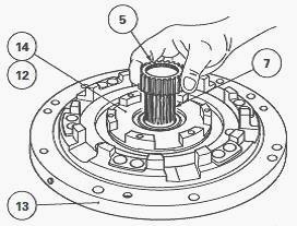
If it proves necessary to replace the bearing (11), force fit a new
bearing (6) with its face flush with
the back end of the bearing.
Degrease the mating faces of the bearing and of the washer (12).
Apply a light coating of Loctite 648 or equivalent to one of the washer faces. Make the washer adhere to the bearing and leave to dry for a few minutes.
Place the bearing on the front cover (13) making sure to align the
lubricating channels. Lightly coat the screws with Loctite 242 and
torque them as follows:
M8 (42) : 20 - 28 Nm - M6 screw (9) : 12 - 16 Nm. Assemble the MF 8240,
8260 transmission shaft (7) via the inside surface of the cover and
the housing (14)
together with the washer (12).
Place the cover on a suitable fixture. Install the Belleville washer (4), a disc (15) and the thrust plate (16). Place the hub (5) on the transmission shaft (7) with the internal grooves facing upwards.
Assemble the discs (3) and the intermediate plates (2). Install the two remaining discs (15) one on each side of the clutch plate (17). Install the springs (20). Check presence of the rivets (74) on the spacer casing (21).
Make sure
the channels in the pistons (22) (37) within the casing (21) are not
blocked.
Lubricate the O’rings (24) (26) and assemble them on the piston (22) and
in the casing (21) respectively.
Position the piston in the casing and fit it using a small plastic
mallet to hit progressively round the edge.
Install the casing (21) on the cover (13). Check that the casing
lubricating channel aligns with that of the cover.
If either the cover (13) or the casing (21) is replaced it is necessary
to check and possibly renew the shimming of the power shuttle front
clutch.
Install the screws (18) and torque to 29 - 37 Nm.
Piston (22) hydraulic test
Connect a pressure gauge fitted with a valve and suitable fixture to the
front piston port. Feed the circuit with compressed air at 0.3 bar.
Close the valve and check
that pressure does not drop over a period of approximately 60 seconds.
Install the bearing (27) on the primary ring gear (31).
Refit the ring gears (31) (34), secondary ring gear carrier (1), bearing
(27) and spring washer (77).
Carry out operations 8 to 11 in reverse order.
In order to avoid any difficulties during assembly, refit the primary
ring gear (31) before tightening the screws (25).
Torque as follows:
- screw (25) : 31 - 35 Nm, Loctite 242
- screw (33) : 13 - 15 Nm, Loctite 242
Lubricate and assemble new O’rings (35) (36). Place the piston (37) in
the casing (21) and force fit it using a small plastic mallet to hit
progressively round the edge.
Piston (37) hydraulic test
- Use a suitable fixture to hold the piston.
- Check seal tightness as for the front piston.
Shimming the planet carriers
For adjusting clearances J1 and J2, springs (65) and clutch plate (38)
must be removed.
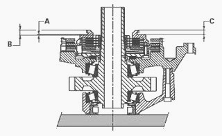
On rear clutch housing
Use a depth gauge to measure dimensions B and C at two opposing points.
Take the average of the two readings. Calculate dimension: A = B - C.
On the planet carrier assembly
Install secondary sun gear (61) complete with retaining ring (49) on
ball bearing (57).
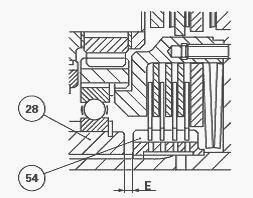
Measure dimension D using a depth gauge.
Determine gap E between primary planet carrier (28) and hub (54)
according to the formula: E = A + D.
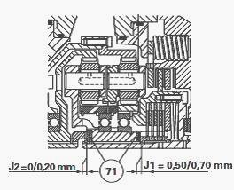
Fill space E with shims (71) having a value of E + 0.50 min. to + 0.70
max., to obtain a clearance of: J1 = E + 0.50 to 0.70 mm.
Adjusting J2 clearance
Place secondary sun gear (61) on housing (59) and the planet carrier
assembly on the shaft (53). Install washer (76) and ring (72).
Position the feeler of a dial gauge and check the clearance by moving
the planet carrier assembly vertically.
Depending on the measured clearance, select the thickness of shims (71)
to obtain J2 = 0 to 0.20 mm.
Remove the planet carrier assembly.
Install springs (65). Position clutch plate (38), ensuring that the
notches align with the tabs of the cover (40).
Ensure presence of shims (71) defined at operation.
Refit secondary sun gear (61) and planet carrier assembly and compress.
Set shims (71) selected at operation against the primary planet carrier
(28). Install washer (76) and ring (72).
Check the secondary sun gear backlash by hand.
Assembling the input unit
Screw two guide studs on the casing (21) (Optional). Check presence of
positioning pin and oil splasher on cover (40).
Use a sling to reinstall the transmission shaft assembly (7), cover (13)
and casing (21) aligning the positioning pin with its housing on the
cover (40).
Turn the shaft in order to engage the planet carriers in the ring gears.
Remove the guide studs (if used). Install the screws (30) and torque to
29 - 37 Nm, having lightly coated the threads with Loctite 242
beforehand.
Check shaft rotation
In case the cover (13) has been replaced, position the ring restrictor
(8) having first lightly coated it with Loctite 648. Check that the
product does not block the
lubricating ports.
Reinstall the power shuttle rear clutch.
Refit the input unit and the power shuttle hydraulic unit. Refit the
clutch cover.
Couple the tractor between the engine and the gearbox.
Top up housings with oil and check the level on the sight-glass on left at rear of central housing. Carry out a road test. Check the oil tightness of the hydraulic unions and of the selector cover mating face.
________________________________________________________________________________
________________________________________________________________________________________
 SPECS
SPECS LOADERS
 MAINTENANCE
 PROBLEMS
________________________________________________________________________________________
 MF 1523
 MF 1531
 MF 135
 MF 1547
 MF 1635
________________________________________________________________________________________
________________________________________________________________________________________
 231
231 231S
231S 235
235 240
240 241
241________________________________________________________________________________________
 255
255 265
265 274
274 285
285 375
375________________________________________________________________________________________
________________________________________________________________________________________
 916X Loader
 921X Loader
 926X Loader
 931X Loader
 936X Loader
________________________________________________________________________________________
 941X Loader
 946X Loader
 951X Loader
 956X Loader
 988 Loader
________________________________________________________________________________________
 1655
1655 GS1705
 1742
1742 2635
2635 4608
4608________________________________________________________________________________________
 1080
1080 1100
1100 2615
2615 3050
3050 3060
3060________________________________________________________________________________________
 4708
4708 5455
5455 5450
5450 5610
5610 5613
5613________________________________________________________________________________________
 DL95 Loader
 DL100 Loader
 DL120 Loader
 DL125 Loader
 DL130 Loader
________________________________________________________________________________________
 DL135 Loader
 DL250 Loader
 DL260 Loader
 L90 Loader
 L100 Loader
________________________________________________________________________________________
 6499
6499 7480
7480 7618
7618 7726
7726 1533
1533________________________________________________________________________________________
 2604H
2604H 2607H
2607H 4455
4455 4610M
4610M 4710
4710________________________________________________________________________________________
 L105E Loader
 L210 Loader
 1014 Loader
 1016 Loader
 1462 Loader
________________________________________________________________________________________
 1525 Loader
 1530 Loader
 232 Loader
 838 Loader
 848 Loader
________________________________________________________________________________________
 5712SL
 6713
6713 6715S
6715S 7475
7475 7615
7615________________________________________________________________________________________
 7716
7716 7724
7724 8240
8240 8650
8650 8732
8732________________________________________________________________________________________
 246 Loader
 1036 Loader
 1038 Loader
 1080 Loader
 856 Loader