
________________________________________________________________________________
Massey Ferguson 8250, 8270 heavy gearbox - Selector rails
Massey Ferguson 8250, 8270 tractors fitted with a Heavy gearbox, the selector rails used for gear selection are located on the right-hand side of the gearbox behind the control cover.
The gear selector comprises four selector rails of which three are for the gearbox and one for the input unit. Each selector rail supports its own fork and respective selector and moves longitudinally in end-bearings.
The forks are adjustable, thus ensuring a functional clearance between
the pads and the synchromesh sliding coupler.
Safety locking of the MF 8250, 8270 gearbox
selector
The system comprises two cylindrical locks of different lengths:
- short locking pin: selector rail 1st - 2nd
- long locking pin: selector rail 3rd - 4th
Their extremities are spherical and one of them has an extended lug.
Each selector rail is machined both to lodge and to allow movement of
the locks.
Operating principle
Example: Ratio 1 engaged - Hare range
When the selector rail is moved to select 1st gear, it forces its lock
to move out of its lodging place and to lock the range selector rail in
the "Hare" position.
At the
same time, this lock pushes another lock that in turn locks the 3rd -
4th selector rail, thus prohibiting any undue movement that might block
the gearbox. The same
reasoning applies to the Tortoise range and other gear ratios.
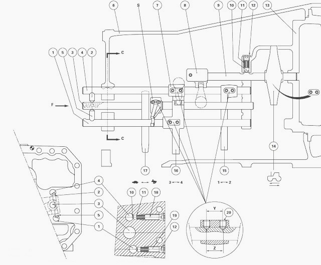
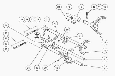
(1) Selector rail 3rd - 4th (2) Short locking pin 1st - 2nd (3) Hare /
Tortoise selector rail (4) Selector rail 1st - 2nd (5) Long locking pin
3rd - 4th (6) Gearbox housing
(7) Selector 1st - 2nd (8) Reverse shuttle selector (9) Reverse shuttle
selector rail (10) Locking pin (11) Spring (12) Plug
(13) Input unit housing (14) Reverse shuttle fork (15) Fork 1st - 2nd
(16) Fork 3rd - 4th (17) Hare / Tortoise fork (18) Long spacer (19)
Short spacer (20) Bolt (21) Pin
Disassembling and reassembling selector rails and adjusting forks and
gearbox selector
Uncouple the MF 8270, 8250 tractor between the gearbox and the
intermediate housing.
Remove the selector cover.
On tractors fitted with a creeper gearbox, the reducer unit located on
the rear face of the gearbox does not hinder disassembly or reassembly
of the selector.
Remove the bolts (20) from the selector (7) and forks (15) (16).
To carry out operations on the 1st - 2nd fork, use a short Allen key due
to the limited space between the fork and the housing.
Disassemble the index assemblies (10) (11) (12) (18).
Push selector rail (4) towards the front and remove lock (2). Proceed in
the same way for selector rail (1) and locking pin (5).
Take out selector rails (1) (4) through the rear of the gearbox.
Using a suitable pin punch, drive out pin (21) from the Hare / Tortoise
fork (17) (Fig. 88).
Take out selector rail (3) through the rear of the housing.
Remove the 3rd - 4th (16) and the Hare / Tortoise forks.
The 1st - 2nd fork (15) cannot be removed from the housing unless the
main shaft has previously been removed.
Clean and inspect the components. Replace any defective parts.
Install the selector rails, forks and selectors in the reverse order of
disassembly.
During refitting, pin (21) on the Hare / Tortoise fork must be replaced
- The short locking pin (2) locks selector rail 1st - 2nd.
- The long locking pin (5) locks selector rail 3rd - 4th.
- The index assembly (10) (11) (12) (18) places selector rail 1st -2nd.
- The index assembly (10) (11) (12) (19) places selector rail 3rd - 4th.
Adjust forks and selector (7)
The positioning of forks (15) (16) and selector (7) is obtained via the
difference between the distance between the centre of threaded holes "Y"
and mark "Z" on the
selector rails (1) (4) (Fig. 87).
A different forward or rearward
movement of the forks is obtained by acting on bolt (20) as required.
The adjustment of forks is carried
out with the gear engaged.
Smear the plugs of the indexing assemblies (10) (11) (12) (18) with Loctite 542 or equivalent and tighten. Lock fork (15) in 1st. Maintain the synchromesh sliding coupler against the pinion.
Check that the rear pads are not in contact
with the synchromesh sliding coupler by slightly moving the selector
rail without moving the
sliding coupler itself.
Repeat the operation (fork locked in 2nd), checking that the rear pads are not in contact with the synchromesh sliding coupler, by using the same method as in operation.
Where necessary, adjust the fork using bolt (20)
previously smeared with Loctite 221 or equivalent.
Proceed in the same way to adjust fork (16).
Tightening torques
- Bolt (20): 35 Nm without modifying its adjustment, Loctite 221.
- Plug (12): 50 - 70 Nm, Loctite 542.
Next, adjust selector (7) in line with the selector incorporated in fork
(16).Adjust the "S" Hare / Tortoise selector.
Install the selector cover. With the gear lever in neutral, check that
locks (2) (5) are free in the rear bearing in the Hare / Tortoise range.
Couple the Massey Ferguson 8270, 8250 tractor between the gearbox and
the intermediate housing.
Road test. Check:
- gear changing
- correct operation of the Hare / Tortoise range.
Check oil tightness of the gearbox and intermediate housing mating
faces, selector cover and hydraulic unions.
Disassembling and reassembling selector rail and adjusting input unit
fork
Uncouple the MF 8250, 8270 tractor between the engine and the gearbox.
Remove the input unit.
Disassemble the indexing assembly (10) (11) (12).
Remove bolt (20) from the reverse shuttle fork (14).
Take out selector rail (9) and fork.
Clean and inspect the components. Replace any defective parts.
Install the fork and selector rail.
Carry out the adjustment of the fork.
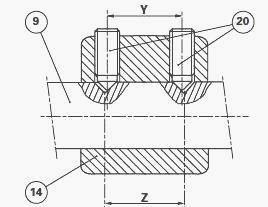
Adjustment
The positioning of fork (14) is obtained by the difference between the
distance between "Y" and mark "Z" on the selector rails (9) (Fig. 89). A
different forward or
rearward movement of the forks is obtained by acting on the forward bolt
(20) or the rear bolt, as required.
Install the locking stud (10), spring (11) and plug (12) tightened to 50
- 70 Nm and previously smeared with Loctite 542 or equivalent. Fit bolt
(20) smeared with
Loctite 221 or equivalent.
Position the fork, locked at the front. Maintain the synchromesh sliding
coupler in thrust against the pinion. Pre-adjust the fork in accordance
with the above
principle.
Check that the front pads are not pinched against the synchromesh
sliding coupler.
Repeat the operation (fork locked at the rear). Check that the rear pads
are not pinched against the synchromesh sliding coupler.
The adjustment is correct when the space is identical between the pads
located on either side of the fork and the synchromesh sliding coupler,
when in the forward
and reverse positions.
Alternatively and progressively tighten bolt (20) to 35 Nm without
modifying its adjustment.
Install the input unit.
Couple the tractor between the engine and the gearbox.
Carry out a road test, checking for the correct operation of the mechanical reverse shuttle. Check for the oil tightness of the selector cover and hydraulic unions.
________________________________________________________________________________
________________________________________________________________________________________
 SPECS
SPECS LOADERS
 MAINTENANCE
 PROBLEMS
________________________________________________________________________________________
 MF 1523
 MF 1531
 MF 135
 MF 1547
 MF 1635
________________________________________________________________________________________
________________________________________________________________________________________
 231
231 231S
231S 235
235 240
240 241
241________________________________________________________________________________________
 255
255 265
265 274
274 285
285 375
375________________________________________________________________________________________
________________________________________________________________________________________
 916X Loader
 921X Loader
 926X Loader
 931X Loader
 936X Loader
________________________________________________________________________________________
 941X Loader
 946X Loader
 951X Loader
 956X Loader
 988 Loader
________________________________________________________________________________________
 1655
1655 GS1705
 1742
1742 2635
2635 4608
4608________________________________________________________________________________________
 1080
1080 1100
1100 2615
2615 3050
3050 3060
3060________________________________________________________________________________________
 4708
4708 5455
5455 5450
5450 5610
5610 5613
5613________________________________________________________________________________________
 DL95 Loader
 DL100 Loader
 DL120 Loader
 DL125 Loader
 DL130 Loader
________________________________________________________________________________________
 DL135 Loader
 DL250 Loader
 DL260 Loader
 L90 Loader
 L100 Loader
________________________________________________________________________________________
 6499
6499 7480
7480 7618
7618 7726
7726 1533
1533________________________________________________________________________________________
 2604H
2604H 2607H
2607H 4455
4455 4610M
4610M 4710
4710________________________________________________________________________________________
 L105E Loader
 L210 Loader
 1014 Loader
 1016 Loader
 1462 Loader
________________________________________________________________________________________
 1525 Loader
 1530 Loader
 232 Loader
 838 Loader
 848 Loader
________________________________________________________________________________________
 5712SL
 6713
6713 6715S
6715S 7475
7475 7615
7615________________________________________________________________________________________
 7716
7716 7724
7724 8240
8240 8650
8650 8732
8732________________________________________________________________________________________
 246 Loader
 1036 Loader
 1038 Loader
 1080 Loader
 856 Loader