
________________________________________________________________________________
Massey Ferguson 5455 Tractor Steering column
Operation of the steering column
The Massey Ferguson 5455, 5460, 5450 Tractor
steering column assembly comprises:
- a fixed lower part composed of a pipe and a body foot;
- a mobile upper part composed of a pipe, a welded stirrup and a unit
containing the steering wheel height and tilt adjustment systems.
Height adjustment
When the control lever (4) is moved upwards, the “T” rod makes the
cranked lever (8) pivot, lowering the arm (15) articulated with the pin
(14).
The screw (5) integral with the arm presses against the brake plate
(16), freeing it and allowing the upper part of the steering column to
move. The spring (3) returns the lever (4) to position. The stop (25)
limits the movement of both parts.
Tilt adjustment
When the control lever (4) is moved downwards, press the T rod which
pushes against the end of the notched lever (9), freeing it from the
steering rack (10) and allowing to tilt the unit (20).
The two return springs (17) facilitate steering wheel positioning. The
screw (5) allows to adjust the meshing of the steering rack (10) with
the notched lever (9).
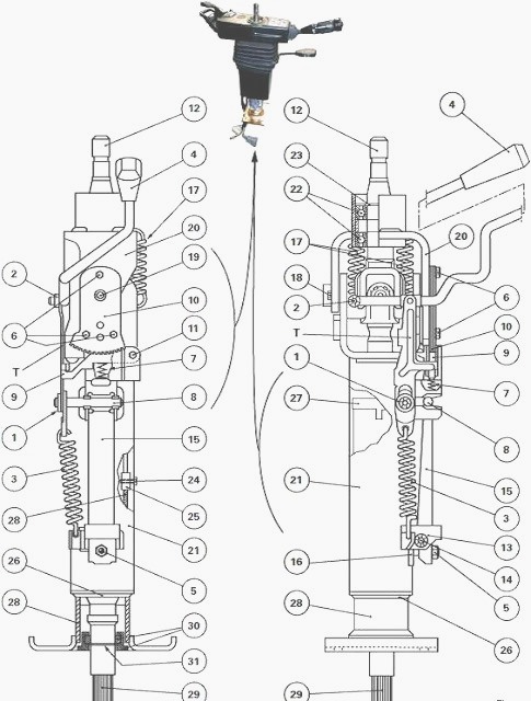
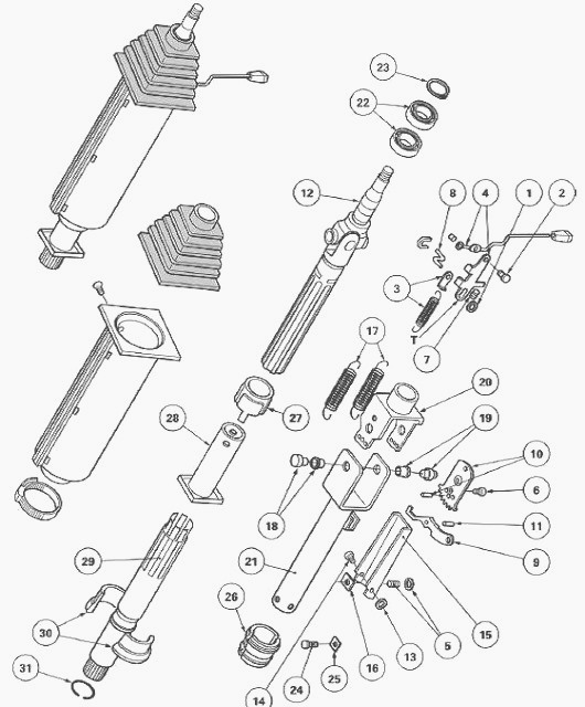
Fig.16/17. Parts list
(1) Retaining washer (2) Retaining washer (3) Spring (4) Control lever
assembly (5) Adjusting screw (6) Screw (7) Spring (8) Cranked lever (9)
Notched lever (10) Steering rack (11) Pin (12) Upper shaft (13)
Retaining washer (14) Pin (15) Arm (16) Brake plate (17) Springs (18)
Pin (19) Pin (20) Housing (21) Mobile column (22) Bearings (23) Circlip
(24) Screw (25) Stop (26) Ring (27) Ring (28) Fixed column (29) Lower
shaft (30) Rings (31) Circlip
Removing and install the MF 5455,
5460, 5450 Tractor steering Column
- Using the lever located to the right under the steering wheel, pull
the steering column as far as possible towards the driver.
- Remove the steering wheel, the instrument panel upper cover and any
components that could hinder steering column removal.
- Disconnect the control connectors (1) placed under the instrument
panel.
- Remove the screws (2) fixing the column base to the cab support.
- Remove the assembly. Check all steering column positions function
correctly.
- Lightly smear the shaft (29) splines with Anti-Seize grease or
equivalent.
- Tighten the steering wheel nut to a torque of 57 - 78 Nm.
- Check the correct operation of electrical equipment.
Removing and installing the control
lever assembly
- Remove the Massey Ferguson 5450, 5460, 5455 Tractor steering column.
- Remove the half housings around the steering column. Remove the Power
Control lever and light switch.
- Remove and discard the retaining washers (1) (2). Remove the spring
(3), lever (4) with seal and lever (8).
- Install the levers (4) (8) and spring (3). Refit the retaining washers
(1) (2).
- Use the adjusting screw (5) to adjust the lever (4) and the T rod in
contact with the notched lever (9). Install the steering column.
Removing and install the notched lever
and the steering rack
- Remove the steering column.
- Remove the half housings around the MF 5455, 5460, 5450 steering
column. Remove the Power Control lever and light switch.
- Remove and discard the retaining washers (1) (2). Remove the spring
(3), lever (4) with seal and lever (8).
- Press on the notched lever (9) to compress the spring (7) Take out the
screws (6). Remove the steering rack (10).
- Drive out the pin (11). Remove the notched lever (9) and the spring
(7).
- Compress the spring (7). Position the steering rack (10) to avoid it
restricting the lever (4). Fit and tighten the screws (6) smeared with
Loctite 242 or equivalent.
- Install the lever (4), T rod and spring (3). Refit the retaining
washers (1) (2).
- Use the adjusting screw (5) to adjust the lever (4) and the T rod in
contact with the notched lever (9). Install the steering column.
Disassembling and assembling the
locking mechanism
- Remove the Massey Ferguson 5455, 5460, 5450 steering column.
- Remove the half housings around the steering column.
- Take out the adjusting screw (5) (3 mm Allen key). Remove and discard
the retaining washer (13).
- Drive out the pin (14). Remove the arm (15) and brake plate (16).
- Install the arm (15) and brake plate (16).
- Install the pin (14). Refit the retaining washer (13).
- Install and adjust the screw (5), lever (4), and T rod in contact with
the notched lever (9). Install the steering column.
Replacing shafts and bearings
- Remove the half housings around the MF 5450, 5460, 5455 Tractor
steering column. Remove the Power Control lever and light switch.
- Slide the seal onto the control lever (4).
- Press on the notched lever (9) to compress the spring (7) Take out the
screws (6). Remove the steering rack (10).
- Remove the springs (17). Loosen the pin (18). Drive out the pins (18)
(19).
- Separate the housing (20) on the mobile column (21).
- Take off circlip (23). Separate the upper shaft (12) from the housing
(20).
- Drive out the lower shaft (29) of the mobile column (21).
- Extract the bearings (22) from the housing (20).
- Use a suitable tool to fit the bearings (22) into the housing (20).
- Assemble the upper shaft (12) on the bearings (22). Fit the circlip
(23).
- Assemble the lower shaft (29) fitted with rings (30) and the circlip
(31) on the fixed column (28).
- Deform the column tube with a punch to lock the rings (30).
- Join the housing (20) and mobile column (21) assemblies. Fit the pins
(18) (19). Tighten the pin (18). Install the springs (17).
- Compress the spring (7). Position the steering rack (10) as shown in
picture to avoid it restricting the lever (4).
- Fit and tighten the screws (6) smeared with Loctite 242 or equivalent.
- Use the adjusting screw (5) to adjust the lever (4) and the T rod in
contact with the notched lever (9). Install the steering column.
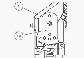
Fig.18
Replacing the guide rings
- Remove the half housings around the steering column.
- Loosen the screw (5). Remove the brake plate (16).
- Remove the screw (24) from the stop (25). Take out the ring (26).
- Split the mobile column (21) from the fixed column (28).
- Take out the ring (27). Position the ring (27).
- Install the stop (25) in the groove of the fixed column (28).
- Assemble the mobile column (21) with the fixed column (28).
- Install the screw (24) without tightening, in order to fit the ring
(26). Once the ring is positioned correctly, moderately tighten the
screw.
- Check that the mobile column (21) slides freely.
- Install the brake plate (16). Use the adjusting screw (5) to adjust
the lever (4) and the T rod in contact with the notched lever (9).
________________________________________________________________________________
________________________________________________________________________________________
 SPECS
SPECS LOADERS
 MAINTENANCE
 PROBLEMS
________________________________________________________________________________________
 MF 1523
 MF 1531
 MF 135
 MF 1547
 MF 1635
________________________________________________________________________________________
________________________________________________________________________________________
 231
231 231S
231S 235
235 240
240 241
241________________________________________________________________________________________
 255
255 265
265 274
274 285
285 375
375________________________________________________________________________________________
________________________________________________________________________________________
 916X Loader
 921X Loader
 926X Loader
 931X Loader
 936X Loader
________________________________________________________________________________________
 941X Loader
 946X Loader
 951X Loader
 956X Loader
 988 Loader
________________________________________________________________________________________
 1655
1655 GS1705
 1742
1742 2635
2635 4608
4608________________________________________________________________________________________
 1080
1080 1100
1100 2615
2615 3050
3050 3060
3060________________________________________________________________________________________
 4708
4708 5455
5455 5450
5450 5610
5610 5613
5613________________________________________________________________________________________
 DL95 Loader
 DL100 Loader
 DL120 Loader
 DL125 Loader
 DL130 Loader
________________________________________________________________________________________
 DL135 Loader
 DL250 Loader
 DL260 Loader
 L90 Loader
 L100 Loader
________________________________________________________________________________________
 6499
6499 7480
7480 7618
7618 7726
7726 1533
1533________________________________________________________________________________________
 2604H
2604H 2607H
2607H 4455
4455 4610M
4610M 4710
4710________________________________________________________________________________________
 L105E Loader
 L210 Loader
 1014 Loader
 1016 Loader
 1462 Loader
________________________________________________________________________________________
 1525 Loader
 1530 Loader
 232 Loader
 838 Loader
 848 Loader
________________________________________________________________________________________
 5712SL
 6713
6713 6715S
6715S 7475
7475 7615
7615________________________________________________________________________________________
 7716
7716 7724
7724 8240
8240 8650
8650 8732
8732________________________________________________________________________________________
 246 Loader
 1036 Loader
 1038 Loader
 1080 Loader
 856 Loader