
________________________________________________________________________________
Massey Ferguson 8280 Tractor hydrostatic steering for 4WD
The steering system on Massey Ferguson 8280, 8270 tractor is of the
dynamic type (constant flowrate of 0.5 l/min, standby pressure of 6
bar). There is no mechanical linkage between the steering wheel and the
steering rams. Its control principle is of the Load Sensing type.
The main components of the circuit are:
- pressurised oil feed from the priority block(s) (depending on version)
supplied by the variable displacement pump,
- an Orbitrol steering distribution valve of the closed centre OSPD.LS
100 - 260 type with twin stator rotors mounted in by-pass.
- two double acting steering rams connected in parallel and mounted on
the 4WD front axles - ZF APL 5052
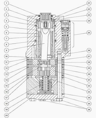
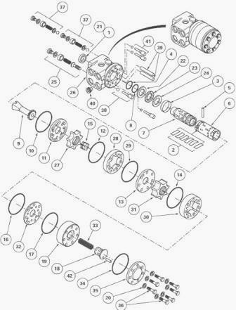
Fig.36/37. MF 8280, 8270 tractor steering construction (Parts
list)
(1) Lip seal, (2) Centring springs, (3) Bush, (4) O’ring, (5) Pin, (6)
Sleeve, (7) Spool valve, (8) O’ring, (9) Linkage shaft, (10) O’ring,
(11) Plate, (12) O’ring, (13) Plate, (14) O’ring, (15) Spacer, (16)
O’ring, (17) O’ring, (18)Integrated spool, (19) Spool body, (20) Seals,
(21) O’ring, (22) Washer, (23) Needle bearings, (24) Washer, (25)
Discharge valve, (26) Block, (27) Rotor (100 cm3), (28) Stator (100
cm3), (29) O’ring, (30) Stator (160 cm3), (31) Rotor (160 cm3), (32)
Plate, (33) Spring, (34) O’ring, (35) Closing plate, (36) Bolts, (37)
Shock valves, (38) Non-return valve, (39) Spacers, (40) One-way valve,
(41) Suction valve, (42) Pin
Disassembling and reassembling the
distribution valve (Orbitrol)
Disassembly MF 8280, 8270 tractor steering
- Remove the distribution valve from the Massey Ferguson 8280, 8270
tractor.
- Place the distribution valve in a vice fitted with plastic jaw
protectors.
- Mark the location of bolts (36). Remove the bolts along with seals
(20).
- Take off the closing plate (35), the O’ring (34), the body (19), the
integral spool (18) and spring (33).
- Remove the O’ring (17). Locate the position of plate (32) and remove
it.
- Remove O’ring (16). Remove stator (30) and rotor (31). Take out the
O’ring (14).
- Locate and remove plate (13).
- Remove spacer (15), stator (28), rotor (27). Locate and remove plate
(11). Take out O’ring (10).
- Take out the splined linkage shaft (9).
- Unscrew the threaded socket and recover the ball from the non-return
valve (38).
- Take out the two pins and the two balls from the Massey Ferguson 8280,
8270 tractor spool valve suction valves (41).
- Extract the sleeve assembly (6) and spool valve (7) by pushing on it
and checking that pin (5) lies along the horizontal axis.
- Take out washers (22) (24), the needle bearings (23) and bush (3) from
the sleeve / spool valve assembly.
- Take out pin (5) and centring springs (2) by pressing on one of their
ends. Separate sleeve (6) from spool valve (7).
- Unscrew the plug of the discharge valve (25). Using an 8 mm Allen key,
disassemble the threaded bush and remove the seal, spring and valve (the
inserted valve seat cannot be removed).
- Unscrew the two plugs from the shock valves (37), remove the seals.
Using a 6 mm Allen key, disassemble the threaded bushes and take out the
springs, the balls and their seats (the inserted valve seats cannot be
removed).
- Extract the oil tightness seal (1) and O’ring (21).
- Disassemble the check valve (40).
Reassembly MF 8280, 8270 tractor steering
- Check and clean all components, replace any parts found to be
defective. Lubricate the components with clean transmission oil before
reassembly.
- Refit the check valve (40). Fit seal (1), O’ring (21) and the bush.
- Fit the balls and springs in the housings of the shock valves (37).
Screw in the threaded bushes, place the seals and tighten the plugs.
- In the housing of the discharge valve (25), place the valve and
spring, screw in the threaded bush. Fit the seal and tighten the plug to
a torque of 40 - 60 Nm.
- Introduce the spool valve (6) in sleeve (7). Position the centring
springs (2) according to Figure 37 and fit pin (5).
- Position bush (3) on the sleeve and spool valve assembly so that the
chamfer facilitates assembly in the spool valve.
- Place washers (22) (24), with the chamfer of washer (24) turned
towards the centring springs (2) and placing needle bearing (23) in
between them.
- Assemble the sleeve and spool valve assembly in the spool valve using
a slight oscillatory movement. Take care that pin (5) is held
horizontally.
- In the suction valve housings (41), place the two balls and the two
pins.
- In the non-return valve housing (38), place the ball and screw in the
threaded bush.
- Position the splined linkage shaft (9). Place the O’ring (10), and the
distributor plate (11).
- Fit rotor (27) so that the two cavities "C" lie in the axis of the
slot of splined shaft (9). Place the O’rings (12) (29) on the stator
(28).
- While avoiding moving the rotor (27), fit the stator (28). Then turn
it so that its fixing holes match those in the spool valve.
- Refit rotor (31) on the spacer (15) so that the two cavities "C" lie
in the axis of the slot of splined shaft (9).
- Place O’rings (14) (16) on the stator (30). Fit and move it so that
the fixing holes match those provided in the spool valve.
- Refit plate (32) in the position noted during disassembly.
- Check that the bore of body (19) and the rim of spool (18) are free of
scratches or burs.
- Check that the spool moves normally in the body.
- Slide the spool fitted with its oil tightness components into the
body. Place O’rings (17) (34) and spring (33). Refit the closing plate
(35).
- Refit the new seals (20) and bolts (36) at the emplacement noted
during disassembly.
- Alternately tighten the bolts to a torque of 30 - 35 Nm.
- Using a test bench or an appropriate fixture, check the adjustment and
operation of the spool valve. Refit the spool valve on the tractor.
- Check the oil tightness of the unions.
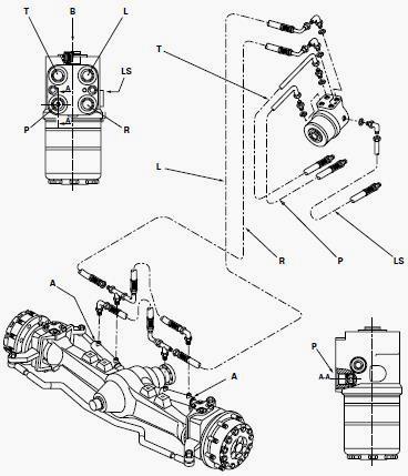
Fig.58. Layout of channels and ports
Disassembling and reassembling Massey
Ferguson MF 8270, 8280 tractor steering ram
Removal
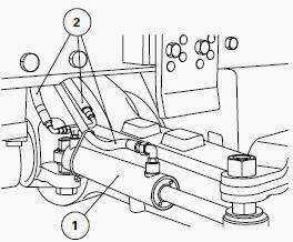
Fig. 55
- Disconnect the hoses (2), carefully noting their positions (Fig.
55-56)
- Loosen and take off nut (4) holding cylinder (3) on the stub (7)
concerned.
- Repeat the previous operation with the fixing point of the piston rod.
- Remove washers (6), spacers (1), carefully noting their positions.
- Remove the ram(s) (1).
- If necessary, take out the circlip(s), remove the ball joint(s) (8).
Refitting
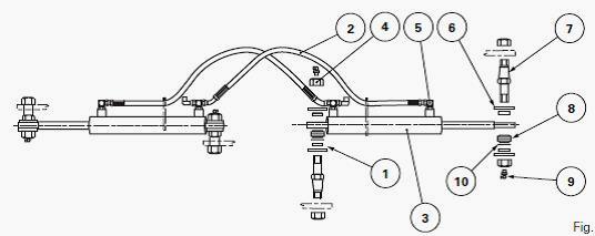
Fig. 56
- If removed, replace the ball joint(s). Fit the circlip(s). (Fig. 56)
- Refit the ram(s), spacer(s) (1) with the chamfer facing the ball joint
and washers (6).
- Fit and tighten the nut(s) (4) to a torque of 440 Nm. Reconnect the
hose pipes (2).
- Using a grease gun and bearing grease, grease the pins (7).
Disassembly
- Take off snap ring (14) by turning the oil tight stuffing box (5)
using a locally manufactured pin wrench. Take out piston rod (15) from
cylinder (3).(Fig. 57)
- Fix the piston rod in a vice using the end intended for holding the
ball joint.
- Loosen and remove nut (2).
- Remove piston (4) and take off O’ring (9).
- Separate the stuffing box (5) from the shaft (15).
Remove:
- from the piston: oil seal (6), bush (7) and O’ring (8).
- from the oil tight stuffing box: O’ring (10), washer (11), oil seal
(12), oil scraper seal (13).
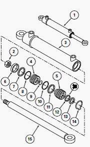
Fig. 57
Reassembly
- Clean and inspect the components. Replace any found to be
defective.(Fig. 57)
- Check that the bore of the cylinder (3) and the rim of the piston (4)
are free from scratches and that the oil passage ports in the cylinder
are not blocked.
- Carefully refit - on the stuffing box (5): oil seal (12), scraper seal
(13), washer (11) and O’ring (10).
- Lubricate the oil seals, O’rings and oil scraper seal.
- Slide the stuffing box in the correct direction on to the shaft (15)
(Fig. 12).
- Refit with care - on piston (4): O’ring (8), bush (7) and oil seal
(6).
- Place a lubricated O’ring (9) against the shoulder of the shaft (15).
- Slide the piston in the correct direction on to the screw cut end of
shaft (15).
- Carry out operation 56 again to grip the piston rod.
- Discard the used nut (2). Fit and tighten a new nut to a torque of 405
Nm.
- Lubricate the bush (7) and the oil seal (6).
- Slide the shaft assembly (15), stuffing box (5) and piston (4) into
cylinder (3).
- Position the machined groove of the stuffing box opposite that of the
cylinder.
- Fit snap ring (14) using the same method as in operation 55.
- Refit the ram(s) on to the tractor.
- Check the operation and the internal oil tightness of the ram(s).
________________________________________________________________________________
________________________________________________________________________________________
 SPECS
SPECS LOADERS
 MAINTENANCE
 PROBLEMS
________________________________________________________________________________________
 MF 1523
 MF 1531
 MF 135
 MF 1547
 MF 1635
________________________________________________________________________________________
________________________________________________________________________________________
 231
231 231S
231S 235
235 240
240 241
241________________________________________________________________________________________
 255
255 265
265 274
274 285
285 375
375________________________________________________________________________________________
________________________________________________________________________________________
 916X Loader
 921X Loader
 926X Loader
 931X Loader
 936X Loader
________________________________________________________________________________________
 941X Loader
 946X Loader
 951X Loader
 956X Loader
 988 Loader
________________________________________________________________________________________
 1655
1655 GS1705
 1742
1742 2635
2635 4608
4608________________________________________________________________________________________
 1080
1080 1100
1100 2615
2615 3050
3050 3060
3060________________________________________________________________________________________
 4708
4708 5455
5455 5450
5450 5610
5610 5613
5613________________________________________________________________________________________
 DL95 Loader
 DL100 Loader
 DL120 Loader
 DL125 Loader
 DL130 Loader
________________________________________________________________________________________
 DL135 Loader
 DL250 Loader
 DL260 Loader
 L90 Loader
 L100 Loader
________________________________________________________________________________________
 6499
6499 7480
7480 7618
7618 7726
7726 1533
1533________________________________________________________________________________________
 2604H
2604H 2607H
2607H 4455
4455 4610M
4610M 4710
4710________________________________________________________________________________________
 L105E Loader
 L210 Loader
 1014 Loader
 1016 Loader
 1462 Loader
________________________________________________________________________________________
 1525 Loader
 1530 Loader
 232 Loader
 838 Loader
 848 Loader
________________________________________________________________________________________
 5712SL
 6713
6713 6715S
6715S 7475
7475 7615
7615________________________________________________________________________________________
 7716
7716 7724
7724 8240
8240 8650
8650 8732
8732________________________________________________________________________________________
 246 Loader
 1036 Loader
 1038 Loader
 1080 Loader
 856 Loader