
________________________________________________________________________________
Case 485, 685 Tractor steering hand pump
Overhaul
To remove the steering hand pump, proceed as follows: On Case IH 485,
685 Tractor without cab, remove battery access panel and disconnect
battery cables. Unbolt and remove upright muffler. Remove radiator cap,
tractor hood and side panels. Remove battery and insulation pad from
battery tray.
Using a suitable puller, remove steering wheel. Remove nut from ignition
switch and push switch to inside. Unbolt and remove instrument panel
side panels. Unbolt instrument panel and raise about 2 inches (50 mm) on
right side and support in this position.
On Case IH 685, 485 Tractor with XL cab, remove battery cover,
disconnect battery cables and remove battery. Using a suitable puller,
remove steering wheel.
Push in and turn lockpins, then lift off the instrument panel front
housing. Loosen locknut and remove engine stop control knob. Remove
locknut and grommet from instrument panel.
Disconnect tachometer cable. Lift instrument panel upward to clear
steering shaft, then move the panel to the right and support assembly in
this position.
On all models, identify and disconnect the four steering hoses from hand
pump. Plug or cap all openings. Remove the two hand pump retaining cap
screws and lower the unit. Remove the two spacers, then remove hand pump
assembly.
To disassemble the steering hand pump, clean exterior of assembly, then
unbolt and remove steering shaft and column. Scribe match marks across
end cover (32—Fig.11), stator (30), distributor plate (27) and housing
(9). Clamp valve housing in a soft jawed vise in inverted position and
remove end cover cap screws.
Remove end cover (32), stator (30), spacer (25), rotor (28), distributor
plate (27) and drive shaft (24). Using a screwdriver and a magnet,
unscrew and remove threaded bushing (14) and ball (13).
Remove unit from vise and shake suction pins (11) and balls (10) from
housing. DO NOT use a magnet to remove pins and balls. Push valve spool
assembly from housing.
Remove thrust washers (16 and 18), needle bearing (17) and retaining
ring (19) from end of spool. Remove cross pin (21) from spool, then
slide spool (20) from sleeve (22). Remove inner and outer plate springs
(23). Remove seal ring (15), "O" ring (12) and dust seal (8) from
housing.
Using an Allen wrench, remove plug (1) with "o" ring (2). Note the
position of the adjusting plug (3), then unscrew while counting the
number of turns needed to remove the adjusting plug.
Record the number of turns to aid in reassembly. Remove spring (4) and
relief valve (5). DO NOT remove seat (6) or check valve (7) as they are
not available as replaceable parts.

Fig.11. Exploded view of the Danfoss steering hand pump
Clean and inspect all parts for excessive wear or other damage. If
housing (9), seat (6), check valve (7), spool (20), sleeve (22), rotor
(28) or stator (30) are not suitable for further service, renew complete
hand pump assembly as these parts are not serviced separately.
All' 'O'' rings, seals and plate springs are available in a seal kit.
Check rotor (28) and stator (30) for wear as follows: Refer to Fig.2 and
measure thickness of rotor at (A) and stator at (B).
If (A) is 0.002 inch (0.051 mm) less than (B), renew hand pump. Refer to
Fig. 12 and place rotor in stator as shown. Using a feeler gage, measure
gap as shown. If gap is 0.005 inch (0.127 mm) or more, renew hand pump
assembly.
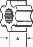
Fig.12. When checking rotor and stator, measure distance "A" on rotor

Fig.13. Distance "B" on stator
Reassemble by reversing the disassembly procedure keeping the following
points in mind. Lubricate all internal parts with Hy-Tran Plus fluid and
coat all "O" rings with
petroleum jelly during reassembly.
When installing plate springs (23—Fig.11), first install the two flat
springs. Then, install the two curved springs (arches back to back) in
between the two flat springs.
When installing rotor (28) on shaft (24), make certain that cross pin
slot in shaft aligns with center of a valley in rotor. Align match marks
and tighten end cover cap
screws (35) to a torque of 22-26 ft.-lbs. (30-35 N-m).
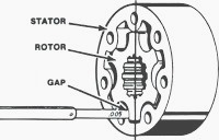
Fig.14. Use a feeler gage to measure gap between rotor and
stator
Reinstall steering column and upper shaft on pump and tighten cap screws
to a torque of 33-37 ft.-lbs. (45-50 N-m). Install hand pump and two
spacers in place, then
install the two retaining cap screws and torque to 33-37 ft.-lbs. (45-50
N-m).
With pump installation completed, install all removed parts (battery,
hood, panels and instrument panel) except access panel to adjust relief
valve (5) pressure.
Refer to paragraph 23 and adjust relief valve pressure as follows:
Remove plug (1—Fig.11) and with engine operating at 1000 rpm, check
relief pressure on gage.
Pressure should be 2150 psi (14825 kPa). Turn adjusting plug (3) inward
to increase pressure or outward to decrease pressure. Install and
tighten plug (1) and
complete balance of installation.
Case 485, 685 Tractor steering hand pump test
To test the steering hand pump, disconnect steering hose from left end
of steering cylinder. Cap cylinder fitting. Connect a hose and 4000 psi
(28000 kPa) test gage to
the steering hose. Remove center cap from steering wheel.

Fig.15. Exploded view of the multiple control valve assembly
With engine stopped, use a torque wrench and apply 52 ft.-lbs. (70 W-m)
of torque to the steering wheel nut in a counterclockwise direction.
Check the reading on the
test gage. Pressure reading should be not less than 55 psi (380 kPa).
If pressure reading is not correct, check for the following conditions:
- Worn Case IH 485, 685 Tractor steering hand pump or damaged seals.
- Worn or stuck cheek ball in hand pump.
- Stuck check valve in pressure inlet port of hand pump.
Then, with engine operating at 1000 rpm, turn steering wheel
counterclockwise and check pressure gage reading. Pressure should read
2150 psi (14825 kPa).
If pressure reading is not correct, check for following conditions:
- Relief valve stuck in hand pump. Incorrect relief valve setting.
- Correct the problem and retest.
- Remove pressure gage and connect steering hose to cylinder.
________________________________________________________________________________
________________________________________________________________________________________
 CASE IH SPECS
 J.I. CASE SPECS
 PROBLEMS
 LOADERS
________________________________________________________________________________________
| CASE IH TRACTORS SPECIFICATIONS |
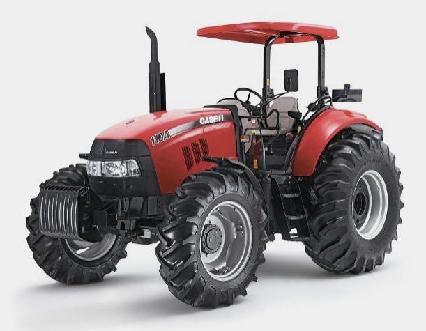 FARMALL 110A
 FARMALL 120A
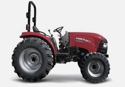 FARMALL 30C
 FARMALL 75C
 MAGNUM 280
________________________________________________________________________________________
 580E Backhoe
 580L Backhoe
 580N Backhoe
 580 Super L
 580SM Backhoe
________________________________________________________________________________________
________________________________________________________________________________________
 580SLE Backhoe
 580SN Backhoe
 580M Backhoe
 580 Super E
 580ST Backhoe
________________________________________________________________________________________
 MAGNUM 310
 MAGNUM 340
 MAXXUM 110CVX
 MAXXUM 120CVX
 MAXXUM 125
________________________________________________________________________________________
 1394
1394 1455XL
 1494
1494 1594
1594 3230
3230________________________________________________________________________________________
 4210
4210 585XL
585XL 633
633 695XL
695XL 733
733________________________________________________________________________________________
 MX110
MX110 MX135
MX135 MX150
MX150 MXU110
 MXU135
________________________________________________________________________________________
 PUMA 175CVX
 PUMA 185CVX
 PUMA 200CVX
 PUMA 240CVX
 OPTUM 300
________________________________________________________________________________________
 FARMALL 50B
 FARMALL 95U
 FARMALL 125A
 PUMA 150
 PUMA 165
________________________________________________________________________________________
 MAGNUM 210
 MX 170
 MAXXUM 150
 OPTUM 270
 MAGNUM 315
________________________________________________________________________________________
 FARMALL 70
 FARMALL 75N
 FARMALL 95C
 FARMALL 105N
 FARMALL 30B
________________________________________________________________________________________
| CASE IH FRONT END LOADERS SPECS |
 L103 Loader
 L104 Loader
 L105 Loader
 L106 Loader
 L107 Loader
________________________________________________________________________________________
 L108 Loader
 L130 Loader
 L160 Loader
 L300 Loader
 L340 Loader
________________________________________________________________________________________
 L350 Loader
 L360 Loader
 L530 Loader
 L540 Loader
 L545 Loader
________________________________________________________________________________________
 L550 Loader
 L555 Loader
 L560 Loader
 L565 Loader
 L570 Loader
________________________________________________________________________________________
 L575 Loader
 L720 Loader
 L730 Loader
 L735 Loader
 L740 Loader
________________________________________________________________________________________
 LRZ 95
 LRZ 100
 LRZ 120
 LRZ 130
 LRZ 150
________________________________________________________________________________________
 L745 Loader
 L750 Loader
 L755 Loader
 L760 Loader
 L765 Loader
________________________________________________________________________________________
 L770 Loader
 L775 Loader
 L780 Loader
 L785 Loader
 L795 Loader
________________________________________________________________________________________
 90 Loader
 890 Loader
 2200 Loader
 2250 Loader
 LX156 Loader
________________________________________________________________________________________