
________________________________________________________________________________
Massey Ferguson 6480 Tractor hydrostatic steering 80/205cm3
The Massey Ferguson 6480, 6485, 6445 Tractor steering system is of the
dynamic type (constant 0.5l /min flow rate - 6 bar standby pressure).
Its control principle is of the Load Sensing (LS) type.
The orbitrol steering unit type is displayed on an adhesive plate
located below the steering unit.
The steering unit has no mechanical links, other than the steering
column itself, between the steering wheel and steering ram.
The system comprises the following main
components:
- a pressurised oil feed from the variable displacement pump;
- a steering unit that can be, according to the type of front axle: OSPDF 80/205 cm3, OSPDF 80/240 cm3;
- a double acting steering ram (1).
The Massey Ferguson 6485, 6445, 6480 Tractor steering unit is supplied
via the priority block(s) (depending on version) by the high flow rate
high pressure circuit.
This circuit also supplies the integrated spool (18) and the two gears
(27)(28), (30)(31).
When the steering wheel is turned, the necessary flow of oil is directed
to the corresponding side of the steering ram. The other side of the ram
is connected to the gearbox selector cover return ports.
In the event of a variable displacement pump failure, only the steering
unit gear (27) (28) acts as a manual pump, thus allowing the tractor to
continue to be steered.
This operation, performed without hydraulic assistance, obviously
requires significant effort to turn the steering wheel.
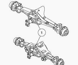
Fig.35
Description of the MF 6480, 6485, 6445
Tractor steering unit
The steering unit comprises:
- two gears of different capacity, each consisting of a rotor and a
stator. These two gears are mechanically coupled to a drive shaft,
itself connected to the steering column;
- a spring centred supply sleeve;
- an integrated spool in the body (19).
The steering unit comprises five ports:
- pressure;
- return to the selector cover;
- two supplies (left and right) to the steering ram;
- Load Sensing
The circuit is protected by a safety valve, two shock valves and two
suction valves.
The principle of Load Sensing
Massey Ferguson 6480, 6485, 6445 Tractor
Steering unit
The LSD steering unit possesses a fifth LS port.
This port is connected:
- either to the closed steering unit circuit when steering is in neutral
position;
- or with the pressure supply line when the steering wheel is turned.
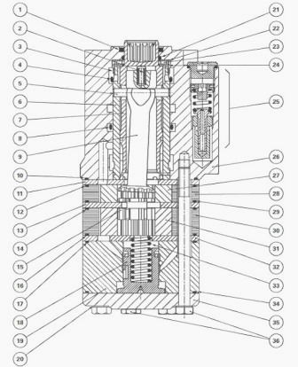
Fig.36. Parts list
(1) Lip seal (2) Centring springs (3) Bush (4) O’ring (5) Cotter pin (6)
Sleeve (7) Spool valve (8) O’ring (9) Link shaft (10) O’ring (11) Plate
(12) O’ring (13) Plate (14) O’ring (15) Spacer (16) O’ring (17) O’ring
(18) Integrated spool (19) Spool body (20) Seals (21) O’ring (22) Washer
(23) Needle bearing (24) Washer (25) Relief valve (26) Orbitrol steering
unit (27) Rotor (gear type 80 cm3) (28) Stator (gear type 80 cm3) (29)
O’ring (30) Stator (gear type 205 cm3 or 240 cm3) (31) Rotor (gear type
205 cm3 or 240 cm3) (32) Plate (33) Spring (34) O’ring (35) Closing
plate (36) Screw
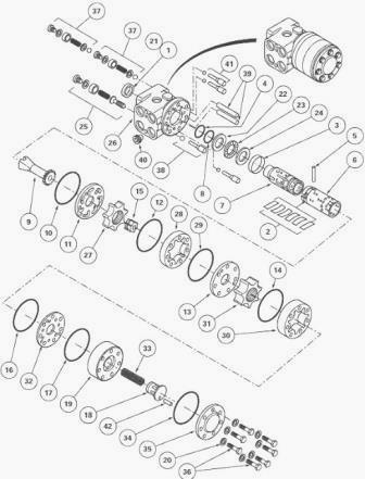
Fig.37. Parts list
(1) Lip seal (2) Centring springs (3) Bush (4) O’ring (5) Cotter pin (6)
Sleeve (7) Spool valve (8) O’ring (9) Link shaft (10) O’ring (11) Plate
(12) O’ring (13) Plate (14) O’ring (15) Spacer (16) O’ring (17) O’ring
(18) Integrated spool (19) Spool body (20) Seals (21) O’ring (22) Washer
(23) Needle bearing (24) Washer (25) Relief valve (26) Orbitrol steering
unit (27) Rotor (gear type 80 cm3) (28) Stator (gear type 80 cm3) (29)
O’ring (30) Stator (gear type 205 cm3 or 240 cm3) (31) Rotor (gear type
205 cm3 or 240 cm3) (32) Plate (33) Spring (34) O’ring (35) Closing
plate (36) Screw (37) Shock valves (38) Non-return valve (39) Spacers
(40) Non-return valve (41) Suction valve (42) Cotter pin
Layout of channels and ports
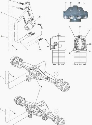
Fig.38. Parts list / Legend
1 - CARRARO fixed 4 WD front axle, 2 - CARRARO suspended 4 WD front
axle, A - Double acting steering ram, B - Location of steering column, L
- Supply to left- hand union of the steering ram, LS - Signal to
variable displacement pump, P - Pressure, R - Supply to right-hand union
of the steering ram, T - Return to housing via gearbox selector cover
Neutral position (engine running)
In this position the spool valve (7) is centred in relation to the
sleeve (6) by the springs (2) (Fig. 7). The channels P1, L, R are not
supplied. The oil coming from the variable displacement pump via channel
(2) is directed in priority to the Orbitrol unit via channel (1).
With the steering in a neutral position, there is no flow in this
channel. The circuit is closed centre. Two shock valves (37) and two
suction valves (41) are located in ports L and R of the spool valve.
The shock valves (37) protect the circuit between the MF 6480, 6485,
6445 Tractor steering ram and the spool valve from eventual pressure
overloads caused by shocks to the wheels.
The suction valves (41) allow the oil released by the shock valves (37)
to pass from the right-hand channel to the left-hand channel or vice
versa depending on the movement of the piston inside the steering ram.
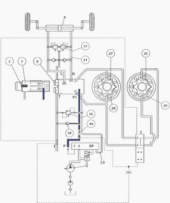
Fig.39. Legend
A - Double acting steering ram, BP - Priority block(s), L - LH hydraulic
port of the steering ram, LS - Signal, P - Pressure, P1 - Supply to
metering devices (stators (28) (30) and rotors (27) (31)), R - RH
hydraulic port of the steering ram, T - Return
Steering on lock position (engine running)
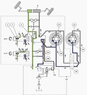
Fig.40
Action on the steering wheel (to the left or right) (Fig. 8) produces an
angular displacement of the spool valve (7) in relation to the sleeve
(6) and the opening of the closed Orbitrol circuit.
A pilot pressure coming from the Orbitrol arrives in channel (4) and
allows the passing into channel (1) of the flow necessary to the
integrated spool (18) and the stator metering devices (stators (28) (30)
and rotors (27) (31)).
The rotors (27) (31) are driven in rotation and force towards the ram a
quantity of oil that is proportional to the degree of rotation. The
rotation of rotors (27) (31) is equal to that of the steering wheel.
Example: Let us suppose that the steering wheel is turned by 5°. An
angular displacement of 5° of the spool valve (7) is produced in
relation to the sleeve (6). The rotors (27) (31) are driven in rotation
as long as they are supplied with pressurised oil.
They drive with them the link shaft (9) and the sleeve (6). When the
latter have turned 5°, the spool valve (7) and the sleeve (6) are once
again centred by the springs (2). The rotors cease to be supplied and
stop. This same reasoning applies to greater angles.
The quantity of oil delivered by the Massey Ferguson MF 6485, 6480, 6445
Tractor steering unit to the steering ram A is therefore proportional to
the rotational angle of the steering wheel.
Depending on whether a left-hand or right-hand lock is applied, the
spool valve (7) directs the oil discharged by the metering devices
(stator (28) (30) and rotor (27) (31)) towards the L or R port.
During rotation, the sleeve (6) ensures the synchronous communication of
the cavities in the metering device with the circuit from the pump, on
the one-hand, and the circuit to the steering rams, on the other hand.
A non-return valve (40) is screwed into the supply port of the steering
unit . This valve is one-way. It prevents excessive pressure exerted to
the front wheels from being transmitted to the pump when the steering
lock is applied.
If the pressure in the steering circuit is too high, the relief valve
(25), located in the steering unit, opens and the excess pressure is
released to channel T.
________________________________________________________________________________
________________________________________________________________________________________
 SPECS
SPECS LOADERS
 MAINTENANCE
 PROBLEMS
________________________________________________________________________________________
 MF 1523
 MF 1531
 MF 135
 MF 1547
 MF 1635
________________________________________________________________________________________
________________________________________________________________________________________
 231
231 231S
231S 235
235 240
240 241
241________________________________________________________________________________________
 255
255 265
265 274
274 285
285 375
375________________________________________________________________________________________
________________________________________________________________________________________
 916X Loader
 921X Loader
 926X Loader
 931X Loader
 936X Loader
________________________________________________________________________________________
 941X Loader
 946X Loader
 951X Loader
 956X Loader
 988 Loader
________________________________________________________________________________________
 1655
1655 GS1705
 1742
1742 2635
2635 4608
4608________________________________________________________________________________________
 1080
1080 1100
1100 2615
2615 3050
3050 3060
3060________________________________________________________________________________________
 4708
4708 5455
5455 5450
5450 5610
5610 5613
5613________________________________________________________________________________________
 DL95 Loader
 DL100 Loader
 DL120 Loader
 DL125 Loader
 DL130 Loader
________________________________________________________________________________________
 DL135 Loader
 DL250 Loader
 DL260 Loader
 L90 Loader
 L100 Loader
________________________________________________________________________________________
 6499
6499 7480
7480 7618
7618 7726
7726 1533
1533________________________________________________________________________________________
 2604H
2604H 2607H
2607H 4455
4455 4610M
4610M 4710
4710________________________________________________________________________________________
 L105E Loader
 L210 Loader
 1014 Loader
 1016 Loader
 1462 Loader
________________________________________________________________________________________
 1525 Loader
 1530 Loader
 232 Loader
 838 Loader
 848 Loader
________________________________________________________________________________________
 5712SL
 6713
6713 6715S
6715S 7475
7475 7615
7615________________________________________________________________________________________
 7716
7716 7724
7724 8240
8240 8650
8650 8732
8732________________________________________________________________________________________
 246 Loader
 1036 Loader
 1038 Loader
 1080 Loader
 856 Loader