________________________________________________________________________________
Case 485, 385 Tractor Speed transmission – 2 speed power shift
Operation
Case 385, 485, 585, 685, 885 Tractors may be equipped with a two speed
Power Shift unit located in front of the speed trans-mission.
The two speed unit is controlled by an electric solenoid/hydraulic
valve.
The two position control switch is located on left side of instrument
panel.
When shifted from high (direct) drive to low drive, tractor power is
increased with a 17 percent reduction in speed in any tractor gear
without interruption of engine power.
This gives the tractor a total of sixteen forward speeds and eight
reverse speeds.
Regulator (control) valve
Overhaul
The regulator (control) valve (4) and bottom core plate (12) can be
removed from Case IH 485, 385 tractor without removing the speed
gearbox.
All other service on the Power Shift unit requires removal of complete
speed gearbox.
![]()
Fig.20. Power Shift regulator (control) valve and bottom core
plate with relative components removed from Case 485, 385 speed
transmission gearbox
1.Screen, 2.Plug, 3.Wire clip, 4.Regulator (control) valve assy, 5."O"
rings, 6.Pressure tubes, 7.Oil inlet tube, 8.Power shift cable,
9.Solenoid cable, 10.Plug, 11.Solenoid wire shield, 12.Bottom core
plate, 13.Gasket, 14.Separator plate, 15.Gasket
To remove the regulator valve and bottom core plate, first disconnect
battery ground cable. Remove drain plug and drain transmission fluid.
On Case 485, 385 tractor equipped with front drive axle, unbolt and
remove drive shaft shield and front drive shaft. On all models, unbolt
and remove solenoid wiring shield (11).
Disconnect the Power Shift cable (8) from solenoid cable (9) at
connector. Unbolt bottom core plate (12) and remove from speed gearbox.
![]()
Fig.21. Regulator (control) valve and solenoid
1.Solenoid, 2."O" ring, 3."O" ring, 4.Screw (2), 5.Clamp, 6.Valve body,
7.Spool, 8.Spring, 9.Plug, 10.Valve, 11.Spring, 12.Pin, 13.Washer,
14.Plug
Disconnect wiring from solenoid, then unscrew union and remove wiring
and union from core plate (12). Remove screws (4), clamp (5) and
solenoid (1) with "o" rings
(2 and 3).
Remove regulator valve end cap (14), washer (13), pin (12), spring (11)
and valve (10). Remove plug (9), spring (8) and spool (7).
Unbolt and remove regulator valve body (6), then remove filter screen
(1) from bottom of valve body. Remove gasket (15), separator plate (14)
and gasket. (13) from
core plate (12).
Remove oil inlet tube (7). Oil tubes (6) will remain in speed gearbox
housing.
Clean and inspect all parts for excessive wear or other damage and renew
as necessary. Body (6), spool (7) and plug (9) are not serviced
separately.
When reassembling, use new "O" rings (2 and 3) and new gaskets (13 and
15) and "O" rings (5) and reverse disassembly procedures.
________________________________________________________________________________
________________________________________________________________________________________
 CASE IH SPECS
 J.I. CASE SPECS
 PROBLEMS
 LOADERS
________________________________________________________________________________________
| CASE IH TRACTORS SPECIFICATIONS |
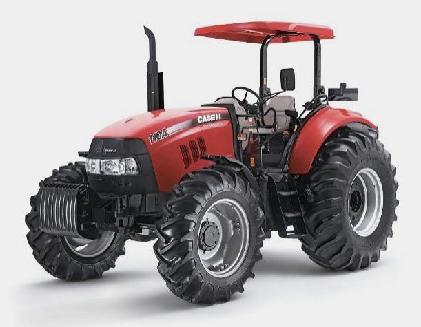 FARMALL 110A
 FARMALL 120A
 FARMALL 30C
 FARMALL 75C
 MAGNUM 280
________________________________________________________________________________________
 580E Backhoe
 580L Backhoe
 580N Backhoe
 580 Super L
 580SM Backhoe
________________________________________________________________________________________
________________________________________________________________________________________
 580SLE Backhoe
 580SN Backhoe
 580M Backhoe
 580 Super E
 580ST Backhoe
________________________________________________________________________________________
 MAGNUM 310
 MAGNUM 340
 MAXXUM 110CVX
 MAXXUM 120CVX
 MAXXUM 125
________________________________________________________________________________________
 1394
1394 1455XL
 1494
1494 1594
1594 3230
3230________________________________________________________________________________________
 4210
4210 585XL
585XL 633
633 695XL
695XL 733
733________________________________________________________________________________________
 MX110
MX110 MX135
MX135 MX150
MX150 MXU110
 MXU135
________________________________________________________________________________________
 PUMA 175CVX
 PUMA 185CVX
 PUMA 200CVX
 PUMA 240CVX
 OPTUM 300
________________________________________________________________________________________
 FARMALL 50B
 FARMALL 95U
 FARMALL 125A
 PUMA 150
 PUMA 165
________________________________________________________________________________________
 MAGNUM 210
 MX 170
 MAXXUM 150
 OPTUM 270
 MAGNUM 315
________________________________________________________________________________________
 FARMALL 70
 FARMALL 75N
 FARMALL 95C
 FARMALL 105N
 FARMALL 30B
________________________________________________________________________________________
| CASE IH FRONT END LOADERS SPECS |
 L103 Loader
 L104 Loader
 L105 Loader
 L106 Loader
 L107 Loader
________________________________________________________________________________________
 L108 Loader
 L130 Loader
 L160 Loader
 L300 Loader
 L340 Loader
________________________________________________________________________________________
 L350 Loader
 L360 Loader
 L530 Loader
 L540 Loader
 L545 Loader
________________________________________________________________________________________
 L550 Loader
 L555 Loader
 L560 Loader
 L565 Loader
 L570 Loader
________________________________________________________________________________________
 L575 Loader
 L720 Loader
 L730 Loader
 L735 Loader
 L740 Loader
________________________________________________________________________________________
 LRZ 95
 LRZ 100
 LRZ 120
 LRZ 130
 LRZ 150
________________________________________________________________________________________
 L745 Loader
 L750 Loader
 L755 Loader
 L760 Loader
 L765 Loader
________________________________________________________________________________________
 L770 Loader
 L775 Loader
 L780 Loader
 L785 Loader
 L795 Loader
________________________________________________________________________________________
 90 Loader
 890 Loader
 2200 Loader
 2250 Loader
 LX156 Loader
________________________________________________________________________________________