________________________________________________________________________________
Power shift transmission of Case 1394, 1390 Tractor – Range gearbox
Disassembly Operations

Fig.45. Case 1390, 1494, 1394, 1690 Tractor Power shift range
transmission showing component parts end their relative positions
1.Spacer, 2.Shim, 3.Bearing, 4.Input shaft, 5.Bearing, 6.Slotted nut,
7.Nut, 8.End plate, 9.Needle roller bearing, 10 Sliding collar gear,
11.Sliding collar, 12.Bearing inner race, 13. Thrust washer, 14.Bearing
inner race, 15.Third range gear, 16.Sliding collar, 17.First range gear,
18.Shim, 19.Pinion shaft, 20.Roll pin, 21.Washer, 22.Bearing, 23.Thrust
washer, 24.Shim, 25.Spacer, 26.Bearing inner race, 27.Second range gear,
28.Needle roller bearing, 29.Reverse range gear, 30.Needle roller
bearing, 31.Sliding collar gear, 32.Bearing inner nice, 33.Needle roller
bearing, 34.Thrust washer, 35.Bearing, 36.Range housing, 37.Shim,
38.Bearing, 39.Idler shaft, 40.Bearing, 41.Second/reverse range shift
rod, 42.Second/reverse shift fork, 43.Shift interlock ping, 44.Detent
spring, 45.Detent ball, 46.First/third range shift rod, 47.First/third
shift fork
Case IH 1394, 1390 Tractor Power shift transmission incorporates a
three-speed range gearbox located directly behind the power shift unit.
Except for removal of bevel pinion shaft (19), range gearbox components
can be serviced after splitting the tractor and removing power shift
unit.
If removal of pinion shaft is required, range
gearbox must be removed from tractor as follows:
- platform or cab (if so equipped).
- fuel tanks. Support tractor with suitable stands, then remove rear
wheels and final drive assemblies.
- differential lock sleeve and spring from right side of rear axle
housing.
- transmission cover and remote valve assembly.
- pto assembly and pto drive shaft. Support rear axle housing with a
hoist, remove mounting bolts securing axle housing to main frame and
remove axle housing.
- transmission mounting bolts and bushings. Attach lifting chain and
hoist to transmission, then move transmission rearward from main frame.
Mount transmission on a stand if available.
- nuts from transmission studs, then separate power shift unit from
range gearbox.
- spacer and sprag clutch from end plate bearing retainer. Drive roll
pin (20) from pinion shaft (19).
- locking nuts (6 and 7) noting that shaft has left-hand threads.
- spacer (21) and bearing (22).
- end cover mounting bolts, then lift end cover (8) from range housing
(36).
- thrust washer (23), shims (24), spacer (25), second gear (27), needle
roller bearings (9) and race (26) from pinion shaft.
- second/reverse shift rod and collar (11) as an assembly.
- gear (10), bearing (28) and race (12), reverse gear (29), thrust
washer (13), third gear (15), bearings (30) and race (14), first/third
shift rail assembly with collar (16) and sliding collar inner gear (31).
Withdraw input shaft assembly (4) and idler shaft assembly (39).
- first gear (17), bearing (33) and race (32) and thrust washer (34).
Mark differential carrier bearing caps to ensure correct reassembly,
then remove caps and differential assembly.
- pinion shaft (19) and rear bearing (35) rearward from range housing.
- neutral start switch, rods and balls from housing.
- shift interlock plug (43), detent ball (45) and spring (44).
Reassembly Operations
Inspect all gears, thrust washers and bearings for excessive wear or
damage and renew as necessary. If renewal of input shaft (4) or idler
gear (39) or their bearings is required, shaft end play must be set as
outlined in following paragraph before reassembling Case IH 1394, 1390
Tractor transmission.
If renewal of pinion shaft (19) or rear bearing is necessary, pinion
shaft protrusion must be set before proceeding with reassembly.
Idler shaft and input shaft end play
Heat bearings to 120°C (250°F) maximum before installing on the shafts.
Install:
- spacer (1) and front bearing cups minus shims (2 and 37) into front
end housing. Position idler shaft and input shaft assemblies into
housing.
- front housing.
Remove the four housing mounting studs, if not already removed, and
install four bolts in place of the studs. Tighten bolts to 95 N-m (70
ft.-lbs.) torque and rotate
shafts to be sure bearings are seated.
Mount a dial indicator so probe contacts end of idler shaft through hole
in front housing. Move shaft up and down and measure end play. Mount
dial indicator so probe
contacts end of input shaft. Move shaft up and down and measure end
play.
Remove front end housing and remove front bearing cups using a suitable
puller.
- shims (2 and 37) in front housing as necessary to obtain 0.05-0.10 mm
(0.002-0.004 inch) end play for each shaft. Reinstall bearing cups in
front housing making
sure they are properly seated. Remove idler shaft and input shaft from
range housing.
Pinion shaft assembly
With pinion shaft protrusion set and pinion shaft installed in housing,
reassemble Case 1390, 1394 Tractor range transmission as follows:
- thrust washer (34) on pinion shaft with oil grooves facing away from
rear bearing.
- first gear (17), bearing (33) and race (32). Position idler shaft and
input shaft assemblies in housing. Position shift interlock plug (43) in
housing bore so it is between
shift rod holes in range housing.
- gear (31) on pinion shaft.
- sliding collar (16) and first/third shift rail assembly. Use tool to
depress detent ball and spring as shift rail is inserted into housing
bore.
- third gear (15), bearings (30) and race (14).
- thrust washer (13) with oil grooves facing away from third gear.
- reverse gear (29), bearing (28) and race (12).
- sliding collar gear (10), sliding collar (11) and second/reverse shift
rail assembly. Use special tool to depress detent ball and spring as
shift rail is pushed into housing
bore.
- second gear (27), bearing (9) and race (26).
- spacer (25) with larger outside diameter against second gear.
- shims (24) removed during disassembly plus an additional 0.25 mm
(0.010 inch) thickness of shims to assure pinion shaft end play.
- thrust washer (23) with flat side of washer against shims.
- end housing (8) with front bearing cup and tighten mounting bolts to
40 N-m (30 ft.-lbs.) torque.
- pinion shaft bearing (22), washer (21) and nut (7). Tighten nut to 271
N-m (200 ft.-lbs.) torque. Mount a dial indicator so probe contacts end
of pinion shaft and
measure shaft end play. Remove pinion shaft bearing retaining nut and
front housing.
Subtract shims from shim pack (24) equal to measured end
play plus an
additional 0.05 mm (0.002 inch) to provide bearing setting within
specified range of zero end play to 0.05 mm (0.002 inch) preload.
With correct thickness shims installed, reinstall front housing,
bearing, washer and retaining nut. Tighten nut to 271 N-m (200 ft.-lbs.)
torque. Install locknut (6) and
tighten to 271 N- m (200 ft.-lbs,) torque, then back nut off to first
slot and install roll pin (20).
Apply Loctite 270 to threads of studs, install studs and tighten to 95
Nm (70 ft.-lbs.) torque. Complete installation by reversing the removal
procedure.
________________________________________________________________________________
________________________________________________________________________________________
| CASE IH TRACTORS SPECIFICATIONS |
________________________________________________________________________________________
________________________________________________________________________________________
________________________________________________________________________________________
________________________________________________________________________________________
________________________________________________________________________________________
________________________________________________________________________________________
________________________________________________________________________________________
________________________________________________________________________________________
________________________________________________________________________________________
________________________________________________________________________________________
________________________________________________________________________________________
| CASE IH FRONT END LOADERS SPECS |
________________________________________________________________________________________
________________________________________________________________________________________
________________________________________________________________________________________
________________________________________________________________________________________
________________________________________________________________________________________
________________________________________________________________________________________
________________________________________________________________________________________
________________________________________________________________________________________
________________________________________________________________________________________

 CASE IH SPECS
 J.I. CASE SPECS
 PROBLEMS
 LOADERS
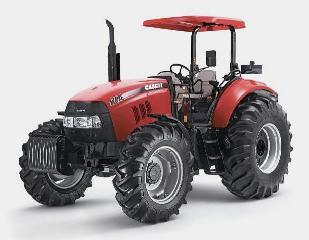 FARMALL 110A
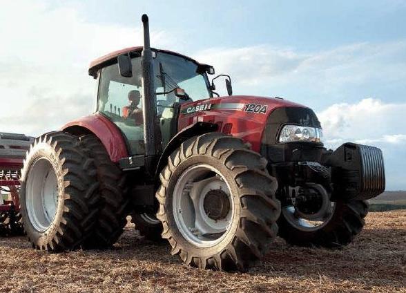 FARMALL 120A
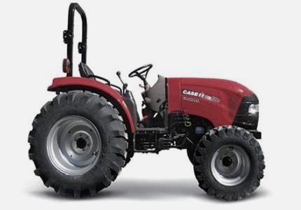 FARMALL 30C
 FARMALL 75C
 MAGNUM 280
 580E Backhoe
 580L Backhoe
 580N Backhoe
 580 Super L
 580SM Backhoe
 580SLE Backhoe
 580SN Backhoe
 580M Backhoe
 580 Super E
 580ST Backhoe
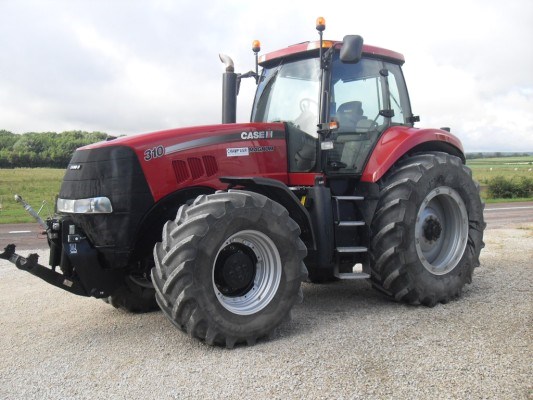 MAGNUM 310
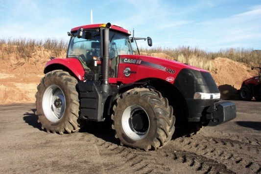 MAGNUM 340
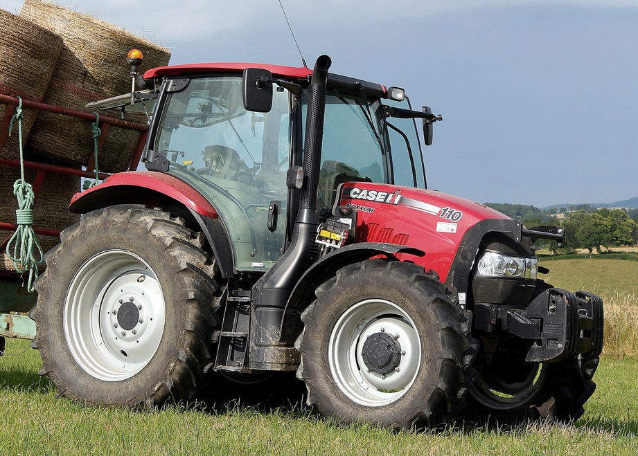 MAXXUM 110CVX
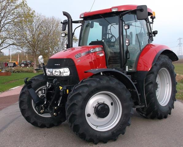 MAXXUM 120CVX
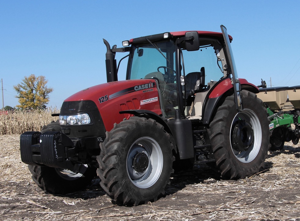 MAXXUM 125
 1394
1394 1455XL
 1494
1494 1594
1594 3230
3230 4210
4210 585XL
585XL 633
633 695XL
695XL 733
733 MX110
MX110 MX135
MX135 MX150
MX150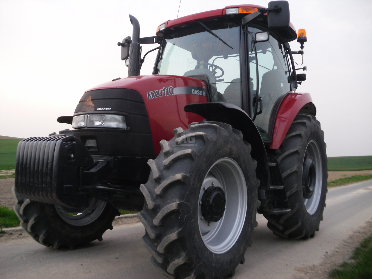 MXU110
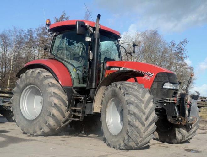 MXU135
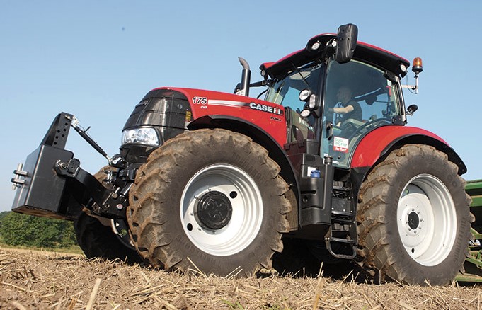 PUMA 175CVX
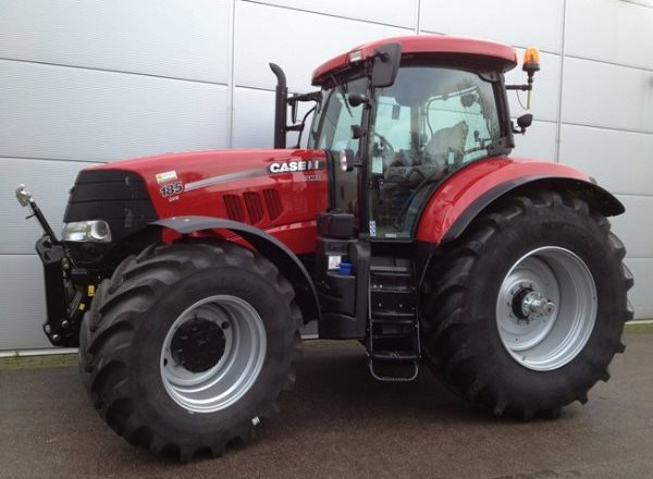 PUMA 185CVX
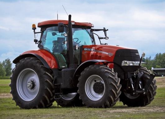 PUMA 200CVX
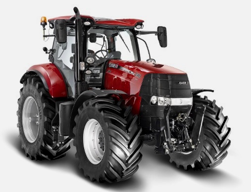 PUMA 240CVX
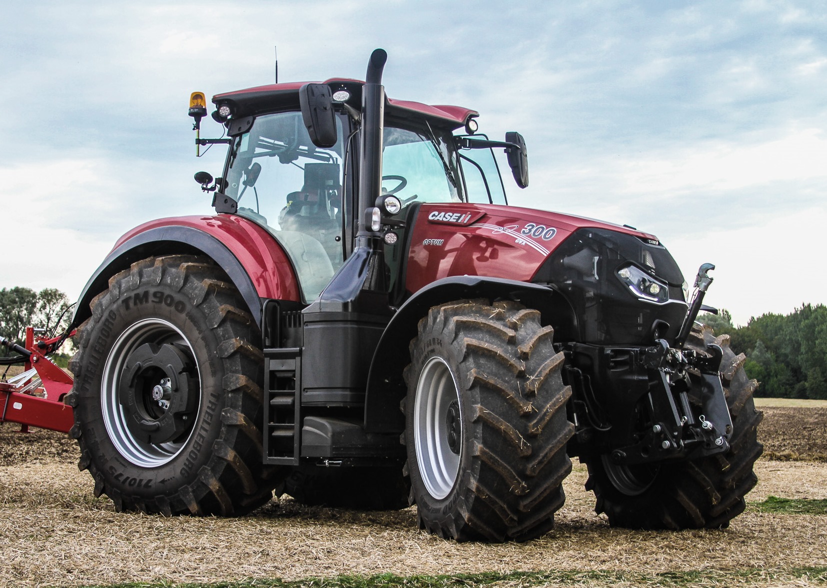 OPTUM 300
 FARMALL 50B
 FARMALL 95U
 FARMALL 125A
 PUMA 150
 PUMA 165
 MAGNUM 210
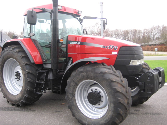 MX 170
 MAXXUM 150
 OPTUM 270
 MAGNUM 315
 FARMALL 70
 FARMALL 75N
 FARMALL 95C
 FARMALL 105N
 FARMALL 30B
 L103 Loader
 L104 Loader
 L105 Loader
 L106 Loader
 L107 Loader
 L108 Loader
 L130 Loader
 L160 Loader
 L300 Loader
 L340 Loader
 L350 Loader
 L360 Loader
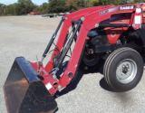 L530 Loader
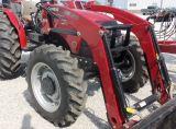 L540 Loader
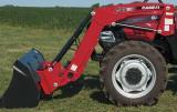 L545 Loader
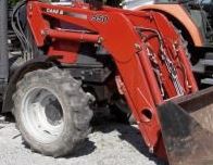 L550 Loader
 L555 Loader
 L560 Loader
 L565 Loader
 L570 Loader
 L575 Loader
 L720 Loader
 L730 Loader
 L735 Loader
 L740 Loader
 LRZ 95
 LRZ 100
 LRZ 120
 LRZ 130
 LRZ 150
 L745 Loader
 L750 Loader
 L755 Loader
 L760 Loader
 L765 Loader
 L770 Loader
 L775 Loader
 L780 Loader
 L785 Loader
 L795 Loader
 90 Loader
 890 Loader
 2200 Loader
 2250 Loader
 LX156 Loader