
________________________________________________________________________________
MF 6465/6480 Tractor PTO driving pinions and Layshaft
On MF 6480, 6465 Tractor the layshaft, clutch, bearings and
driving pinion form the upper shaft line of the rear power take-off PTO.
The upper shaft line passes through the intermediate and centre housings
to then transmit the engine speed to the driving pinions located in the
rear housing.
The layshaft is supported at the front by a bearing block mounted on two
ball bearings housed in the bore of the intermediate housing and at the
rear by the clutch assembly (15) in which the driving pinions are
integral via splines.
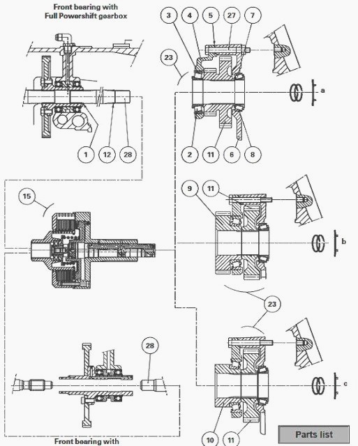
Fig.40. Parts list
(1) Circlip, (2) Bearing cone, (3) Bearing cup, (4) Cover, (5) Shims,
(6) Unit housing, (7) Bearing cone, (8) Bearing cup, (9) Driving pinion,
(10) Spacer, (11) Driving, pinion(s), (12) Circlip, (27) Bolt, (28)
Layshaft
On unit (23), the cups (3) (8) are free mounted in their respective
bores. The bearing cone (7) is mounted free on the splined part of the
clutch.
Depending on the type of power take-off, the
bearing cone (2) is force fitted on:
- the clutch unit (15)
- the pinion (9)
- the spacer (10)
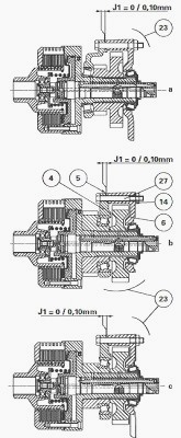
Identification of the assemblies corresponding
to the types of power take-off PTO available
"a" : removable shaft
"b" : jaw coupler
"c" : 1000 rpm
Uncouple the power take-off PTO housing from
the centre housing to carry out maintenance on the following components:
- driving pinion(s)
- unit housing (6)
- cover (4)
- bearings (2) (3) and (7) (8)
Removing and installing the driving
pinion, bearings and layshaft
Special points (Fig.40)
- If the layshaft (28) mounted on tractors fitted with Powershift
transmission has to be replaced, it is absolutely necessary to remove
the left-hand side hydraulic cover to gain access to circlip (1), since
this will not pass through the hole provided in the wall of the
intermediate housing. Before removing the shaft, visually note its
profile in order to later pass the crownwheel of the bevel gear through.
- On Massey Ferguson 6480, 6465 Tractor fitted with Heavy
Duty transmission, the layshaft does not has a circlip (1).
Removal
Remove and separate the clutch (15) and unit (23) assembly.
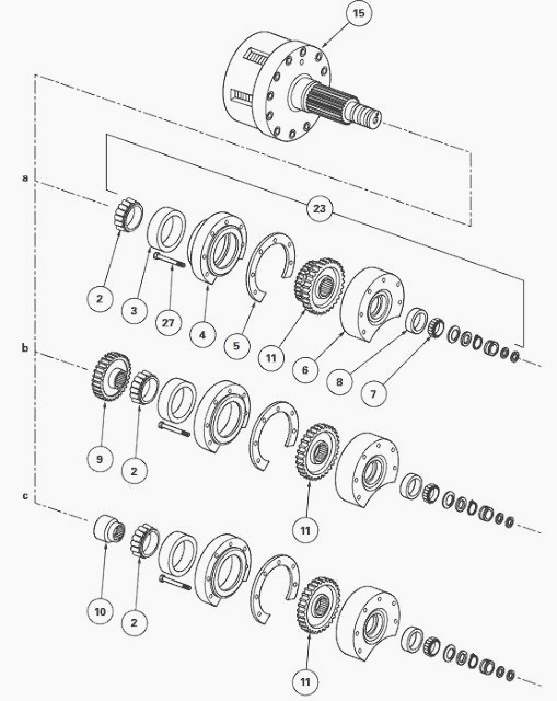
Assembly PTO type "a" (Fig.41-42)
Extract bearing cone (2) from the clutch unit and remove it. Take off
bolts (27), cover (4) and shim(s) (5).
Take out the driving pinion (11) from unit (6).
Disassemble the cups (3) (8) (as required).
Assembly PTO type "b" (Fig41-43)
Remove pinion (9) and bearing cone (2). Take out cup (3) from the cover
(4).
Remove the cover and shim(s) (5).
Take out cup (8) from unit (6). Extract cone (2) (as required).
Assembly Massey Fergusson 6465,
6480 Tractor PTO type "c" (Fig.41)
- On this type of assembly, the method is similar to that used for
assembly "b" type.
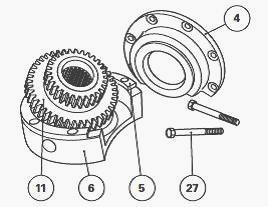
Refitting
- If maintenance has been carried out on one of the components stated at
the beginning of this section, it is important to carry out shimming of
the bearings (2) (3) and (7) (8).
Assembly PTO "a"
If disassembled, place cups (3) and (8) in cover (4) and unit (6)
respectively.
Install the driving pinion (11), the shim(s) (5) (if adjustment is not
necessary), the cover (4) and the bolts (27) on unit (6).
Using a press and an appropriate fixture, insert bearing cone (2) into
the clutch housing.
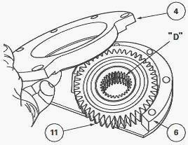
Assembly PTO "b"
If disassembled, place cups (3) and (8) in cover (4) and unit (6)
respectively.
Position pinion (11) in unit (6), the long offset "D" turned to face
cover (4) (Fig.1-4).
Install the shim(s) (5) (if adjustment is not necessary), the cover (4)
and bolts (27) on unit (6).
Using a press and an appropriate fixture, insert bearing cone (2) in
pinion (9).
Assembly PTO "c"
- In this type of assembly, assemble the components using the assembly
principle used in the “b” type assembly.
Reassemble and refit clutch (15) and unit (23) assembly.
Shimming
Assemble MF 6480, 6465 Tractor clutch (15) with unit (23).
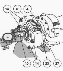
Fasten the cover (4) and the unit housing (6) with four bolts (27) and
nuts (14) that should be supplied locally (Figs. 44-45). Hold the
assembly (23) in a vice fitted with soft jaws (Fig. 44).
Place the index of a dial gauge on the end of the sleeve (10).
Pull hard on the clutch unit while turning it alternatively left and
right in order to correctly seat the cones in the cups.
Reset the dial gauge to zero.
Pull hard on the clutch unit while turning it alternatively left and
right in order to correctly seat the cones in the cups, but this time by
pushing.
According to the provisional clearance measured on the dial gauge,
determine a new thickness of shim(s) (5) to obtain a definitive
clearance (Fig.45): J1 = 0 to 0.10 mm.
________________________________________________________________________________
________________________________________________________________________________________
 SPECS
SPECS LOADERS
 MAINTENANCE
 PROBLEMS
________________________________________________________________________________________
 MF 1523
 MF 1531
 MF 135
 MF 1547
 MF 1635
________________________________________________________________________________________
________________________________________________________________________________________
 231
231 231S
231S 235
235 240
240 241
241________________________________________________________________________________________
 255
255 265
265 274
274 285
285 375
375________________________________________________________________________________________
________________________________________________________________________________________
 916X Loader
 921X Loader
 926X Loader
 931X Loader
 936X Loader
________________________________________________________________________________________
 941X Loader
 946X Loader
 951X Loader
 956X Loader
 988 Loader
________________________________________________________________________________________
 1655
1655 GS1705
 1742
1742 2635
2635 4608
4608________________________________________________________________________________________
 1080
1080 1100
1100 2615
2615 3050
3050 3060
3060________________________________________________________________________________________
 4708
4708 5455
5455 5450
5450 5610
5610 5613
5613________________________________________________________________________________________
 DL95 Loader
 DL100 Loader
 DL120 Loader
 DL125 Loader
 DL130 Loader
________________________________________________________________________________________
 DL135 Loader
 DL250 Loader
 DL260 Loader
 L90 Loader
 L100 Loader
________________________________________________________________________________________
 6499
6499 7480
7480 7618
7618 7726
7726 1533
1533________________________________________________________________________________________
 2604H
2604H 2607H
2607H 4455
4455 4610M
4610M 4710
4710________________________________________________________________________________________
 L105E Loader
 L210 Loader
 1014 Loader
 1016 Loader
 1462 Loader
________________________________________________________________________________________
 1525 Loader
 1530 Loader
 232 Loader
 838 Loader
 848 Loader
________________________________________________________________________________________
 5712SL
 6713
6713 6715S
6715S 7475
7475 7615
7615________________________________________________________________________________________
 7716
7716 7724
7724 8240
8240 8650
8650 8732
8732________________________________________________________________________________________
 246 Loader
 1036 Loader
 1038 Loader
 1080 Loader
 856 Loader