
________________________________________________________________________________
1106 Perkins motor - Turbocharger (Repair operations)
Removal Procedure (Side Mounted)
Care must be taken to ensure that fluids are contained during
performance of inspection, maintenance, testing, adjusting and repair of
the product. Be prepared to collect the fluid with suitable containers
before opening any compartment or disassembling any component containing
fluids. Dispose of all fluids according to local regulations and
mandates. Disconnect the air hose for the turbocharger inlet and for the
turbocharger outlet. If the turbocharger has a remote wastegate
solenoid, disconnect the hose to the solenoid from the turbocharger.
Disconnect the exhaust pipe. If the turbocharger has an exhaust elbow,
remove the exhaust elbow.
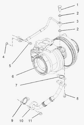
Follow Steps to remove the tube assembly (4) for the oil feed. Remove
the setscrew (5). Remove the banjo bolt (1) and remove the two sealing
washers (2). Discard the sealing washers. Remove the tube assembly (3)
from the cylinder block. Remove the O-ring seal (4) from the tube
assembly. Discard the O-ring seal. Plug the port for the oil feed to the
turbocharger with a suitable plug. Remove the tube assembly (10) for the
oil drain. Remove the two setscrews (11). Remove the two setscrews (8)
and remove the tube assembly (10) from the turbocharger (6). Remove the
joint (7) and remove the joint (9). Discard the joints.
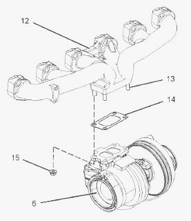
Remove the four nuts (15) from the turbocharger (6) and remove the
turbocharger (6) from the exhaust manifold (12). Ensure that the weight
of the turbocharger is supported as the nuts are loosened. Remove the
joint (14). Discard the joint. If necessary, remove the four studs (13)
from the exhaust manifold (12).
Removal Procedure (Top Mounted)
Disconnect the air hose for the turbocharger inlet and for the
turbocharger outlet. If the turbocharger has a remote wastegate
solenoid, disconnect the hose to the solenoid from the turbocharger.
Disconnect the exhaust pipe. If the turbocharger has an exhaust elbow,
remove the exhaust elbow.
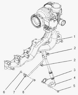
Remove the two setscrews (5) in order to disconnect the tube assembly
(4) from the cylinder block. Remove the joint (3). Discard the joint.
Remove the setscrew (8) in order to disconnect the tube assembly (7)
from the cylinder block. Remove the fasteners for the tube clips (2).
Loosen the four nuts (11). Refer to Illustration. Remove the exhaust
manifold (1) and the assembly of the turbocharger from the cylinder
head.
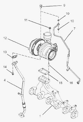
Remove the banjo bolt (9) and remove the tube assembly (7) for the oil
feed from the turbocharger (12). Remove the two sealing washers (10).
Discard the sealing washers. Remove the O-ring seal (6) from the tube
assembly (7). Refer to Illustration. Discard the O-ring seal. Remove the
two setscrews (14) and remove the tube assembly (4) for the oil drain
from the turbocharger (12). Remove the joint (13). Discard the joint.
Remove the four nuts (11) and remove the turbocharger (12) from the
exhaust manifold (1). Remove the joint (15) from the exhaust manifold
(1). Discard the joint. If necessary, remove the four studs (16) from
the exhaust manifold (1).
Disassemble and Assemble Procedures
Disconnect the pipe for the boost sensor (7) at the actuator (6). Remove
the circlip (1) that retains the actuator rod (4). Remove the actuator
rod (4) from the pin (2). Remove the nuts (5) from the bracket (3).
Remove the actuator (6) from the bracket (3). Do not attempt to
disassemble the turbocharger cartridge assembly or wastegate. Do not
remove the compressor wheel. The turbocharger cartridge assembly and the
wastegate are not field serviced, and should be replaced only as a unit.
Install the actuator (6) to the bracket (3). Install the nuts (5) to the
bracket (3). Tighten the nuts to a torque of 5 Nm (44 lb in). Connect
the bottom of the actuator (6) to a suitable air supply with an accurate
gauge. Operate the arm of the actuator by hand in order to check that
the valve is free to move. Push the arm of the wastegate valve toward
the actuator (6) and hold the arm in position. Slowly apply air pressure
to the actuator (6) until the pin (2) will fit into the actuator rod
(4). Install the circlip (1) into the groove in the pin (2). Do not
apply an air pressure of more than 205 kPa (29 psi) to the actuator.
High pressures may damage the actuator. Install the pipe for the boost
pressure (7) to the actuator (6).
Installation Procedure (Side Mounted)
Ensure that the turbocharger is clean and free from damage. Inspect the
turbocharger for wear. If any part of the turbocharger is worn or
damaged, the complete turbocharger must be replaced. Test the wastegate
actuator (19) for correct operation. If the wastegate actuator is
damaged or the wastegate actuator does not operate within the specified
limits, the wastegate actuator must be replaced.
Clean the mating surfaces of the exhaust manifold (12). If necessary,
install the four studs (13) to the exhaust manifold. Tighten the studs
to a torque of 18 Nm (13 lb ft). Install a new joint (14) to the exhaust
manifold (12). Position the turbocharger (6) on the exhaust manifold.
Ensure that the turbocharger is correctly oriented. Install the four
nuts (15). Tighten the nuts to a torque of 44 N·m (32 lb ft). If a new
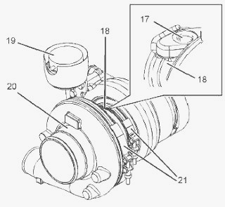
turbocharger is installed, the bearing housing (18) and the compressor
housing (20) must be oriented to the correct positions.
Loosen the two band clamps (21) sufficiently in order to allow the
housings to rotate. If the band clamps are damaged, replace the band
clamps. Carefully turn the bearing housing (18) until the port for the
oil feed (17) is upward. Rotate the compressor housing (20) until the
compressor outlet is in the correct position. Ensure that the band
clamps (21) are correctly oriented. Tighten the band clamps finger
tight.
Ensure that the tube assemblies (3) and (10) are clean and free from
damage. Replace any damaged components. Position a new joint (7) and the
two setscrews (8) onto the tube assembly (10). Install the tube assembly
(10) to the turbocharger (6). Tighten the setscrews (8) finger tight.
Position a new joint (9) between the flange of the tube assembly (10)
and the cylinder block. Install the two setscrews (11) finger tight. If
a new turbocharger has been installed, check that the orientation of the
bearing housing (18) is correct. If the orientation of the bearing
housing is not correct, rotate the bearing housing until the tube
assembly (10) fits correctly. Tighten the two band clamps (21) to a
torque of 13 Nm (9.6 lb ft). Tighten the setscrews (8) and (11) to a
torque of 22 Nm (16 lb ft).
Remove the plug from the oil inlet port (17). Lubricate the turbocharger
bearings with clean engine oil through the oil inlet port. Rotate the
wheel of the compressor several times in order to lubricate the
bearings. Use Tooling in order to lubricate a new O-ring seal (4).
Install the O-ring seal (4) to the tube assembly (3). Install the banjo
bolt (1) and two new sealing washers (2) to the tube assembly (3).
Install the tube assembly (3) to the cylinder block and to the
turbocharger (6). Tighten the banjo bolt (1) finger tight.
Install the setscrew (5) finger tight. Ensure that the tube assembly (3)
fits correctly. Tighten the banjo bolt (1) to a torque of 20 Nm (14 lb
ft). Tighten the setscrew (5) and (11) to a torque of 22 Nm (16 lb ft).
If the turbocharger has an exhaust elbow, install the exhaust elbow.
Connect the exhaust pipe. If the turbocharger has a remote wastegate
solenoid, connect the hose for the solenoid to the turbocharger. Connect
the air inlet hose and connect the air outlet hose to the turbocharger.
Installation Procedure (Top Mounted)
Ensure that the turbocharger is clean and free from damage. Inspect the
turbocharger for wear. If the turbocharger is worn, the complete
turbocharger must be replaced. Test the wastegate actuator (19) for
correct operation. If the wastegate actuator is damaged or the wastegate
actuator does not operate within the specified limits, the wastegate
actuator must be replaced. Clean the mating surfaces of the exhaust
manifold (1). If necessary, install the four studs (16) to the exhaust
manifold. Tighten the studs to a torque of 18 Nm (13 lb ft). Support the
exhaust manifold during installation of the turbocharger. Install a new
joint (15) to the exhaust manifold (1).
Position the turbocharger (12) on the exhaust manifold (1). Install the
four nuts (11). Tighten the nuts to a torque of 44 Nm (32 lb ft). If a
new turbocharger is installed, the bearing housing (18) and the
compressor housing (20) must be oriented to the correct positions.
Loosen the two band clamps (21) sufficiently in order to allow the
housings to rotate. If the band clamps are damaged, replace the band
clamps. Carefully turn the bearing housing (18) until the port for the
oil feed (17) is upward. Rotate the compressor housing (20) until the
compressor outlet is in the correct position. Ensure that the band
clamps (21) are correctly oriented. Tighten the band clamps finger
tight.
Ensure that the tube assemblies (4) and (7) are clean and free from
damage. Replace any damaged components. Position a new joint (13) and
the two setscrews (14) onto the tube assembly (4). Install the tube
assembly (4) to the turbocharger (12). Tighten the setscrews (14) finger
tight. Remove the plug from the oil inlet port (17). Lubricate the
turbocharger bearings with clean engine oil through the oil inlet port.
Rotate the wheel of the compressor several times in order to lubricate
the bearings. Install the banjo bolt (9) and two new sealing washers
(10) to the tube assembly (7). Use Tooling in order to lubricate a new
O-ring seal (6). Install the O-ring seal (6) to the tube assembly (7).
Install the tube assembly (7) to the turbocharger (12). Tighten the
banjo bolt (9) finger tight.
Install the exhaust manifold (1) and the assembly of the turbocharger to
the cylinder head. Install the setscrew (8) finger tight. Ensure that
the tube assembly (7) fits correctly. Position a new joint (3) between
the flange of the tube assembly (4) and the cylinder block. Install the
two setscrews (5) finger tight. If a new turbocharger has been
installed, check that the orientation of the bearing housing (18) is
correct. If the orientation of the bearing housing is not correct,
rotate the bearing housing until the tube assemblies (4) and (7) fit
correctly. Tighten the two band clamps (21) to a torque of 13 Nm (9.6 lb
ft). Tighten the banjo bolt (9) to a torque of 20 Nm (14 lb ft). Tighten
the setscrew (5) and (8) to a torque of 22 Nm (16 lb ft). Install the
fasteners for the tube clips (2) to the cylinder block.
If the turbocharger has an exhaust elbow, install the exhaust elbow.
Connect the exhaust pipe.
________________________________________________________________________________
________________________________________________________________________________________
 SPECS
SPECS LOADERS
 MAINTENANCE
 PROBLEMS
________________________________________________________________________________________
 MF 1523
 MF 1531
 MF 135
 MF 1547
 MF 1635
________________________________________________________________________________________
________________________________________________________________________________________
 231
231 231S
231S 235
235 240
240 241
241________________________________________________________________________________________
 255
255 265
265 274
274 285
285 375
375________________________________________________________________________________________
________________________________________________________________________________________
 916X Loader
 921X Loader
 926X Loader
 931X Loader
 936X Loader
________________________________________________________________________________________
 941X Loader
 946X Loader
 951X Loader
 956X Loader
 988 Loader
________________________________________________________________________________________
 1655
1655 GS1705
 1742
1742 2635
2635 4608
4608________________________________________________________________________________________
 1080
1080 1100
1100 2615
2615 3050
3050 3060
3060________________________________________________________________________________________
 4708
4708 5455
5455 5450
5450 5610
5610 5613
5613________________________________________________________________________________________
 DL95 Loader
 DL100 Loader
 DL120 Loader
 DL125 Loader
 DL130 Loader
________________________________________________________________________________________
 DL135 Loader
 DL250 Loader
 DL260 Loader
 L90 Loader
 L100 Loader
________________________________________________________________________________________
 6499
6499 7480
7480 7618
7618 7726
7726 1533
1533________________________________________________________________________________________
 2604H
2604H 2607H
2607H 4455
4455 4610M
4610M 4710
4710________________________________________________________________________________________
 L105E Loader
 L210 Loader
 1014 Loader
 1016 Loader
 1462 Loader
________________________________________________________________________________________
 1525 Loader
 1530 Loader
 232 Loader
 838 Loader
 848 Loader
________________________________________________________________________________________
 5712SL
 6713
6713 6715S
6715S 7475
7475 7615
7615________________________________________________________________________________________
 7716
7716 7724
7724 8240
8240 8650
8650 8732
8732________________________________________________________________________________________
 246 Loader
 1036 Loader
 1038 Loader
 1080 Loader
 856 Loader