
________________________________________________________________________________
Massey Ferguson 7715, 7718 Load sending and twin flow load sending - Lift control spool valve
The function of the MF 7715, 7718 lift control valve is to regulate the oil flow to and from the lift rams according to the signals transmitted by the ELC calculator.
The lift control valve contains an LS port for the Load Sensing system. This pilot port allows the valve to send pressure data to the regulator via the priority block(s).
This lift control valve is made up of elements themselves comprising
spools and valves. Some of the elements cannot be repaired as spare
parts.
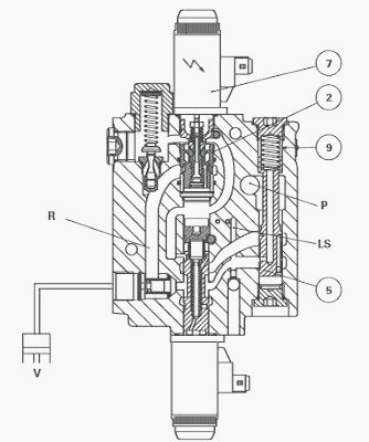
Layout of components and identification of ports
The Bosch/Rexroth lift control valve consists of two parts: Hydraulic
part (spool valve) and Electrical part (solenoid valves).
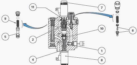
Hydraulic part (spool valve) - (1) Non-return valve, maintaining the oil
in the rams (2) Spool valve assembly used in the lowering phase (4)
Control spool valve (5) Flow regulating spool valve (6) Shock valve (9)
Flow regulating spool spring (10) Control spool spring (11) Spool valve
assembly spring, Electrical part (solenoid valves) - (7) Lowering
solenoid valve (8) Lifting solenoid valve
In order to determine whether the fault is of hydraulic or electric
type, press the push-buttons at the ends of the solenoid valves; this
eliminates the electronic effect of the lift function.
Identification of ports (GPA20 and GPA40
rear axles)
On the inlet block
HP supply from the two-cylinder pump via the priority block(s)
(depending on model)
LS signal to the balance block via the priority block(s)
On the lift control valve
Rams return pipe or hose to housing
HP ram supply
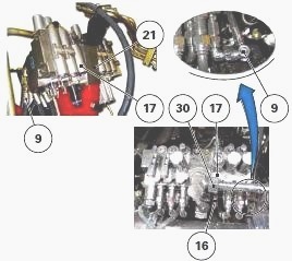
Identification of ports (GPA30 rear axle)
On the right-hand end plate - (9) LS hose from the priority block(s)
On the oil manifold (21) - (30) High pressure hose from the priority
block(s)
On the lift control valve (17) - (16) Lift ram supply pipes
Removing - install the spool valve block and the lift control valve
(GPA30 rear axle)
Removing the Massey Ferguson 7715, 7718 auxiliary spool valves
Remove the complete auxiliary spool valve block/lift control valve in
order to reach the lift control valve under optimum conditions of
cleanliness.
Install the spool valve block.
Reinstall the complete auxiliary spool valve block/lift control valve.
If necessary, carry out the hydraulic tests related to the operations
performed.
Disassembling and Reassembling the MF 7715, 7718 lift control valve
Carefully clean the complete auxiliary spool valve block/lift control
valve before carrying out servicing.
Split the components of the auxiliary spool valve block down to the lift
control valve.
Reassemble the complete auxiliary spool valve block/lift control valve.
Neutral position
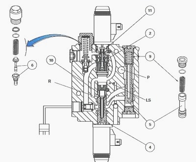
When the Massey Ferguson 7715, 7718 tractor engine is not running and
the spool valve is in the neutral position, the control spool (4) and
the spool valve assembly (2) are maintained respectively by the springs
(10) and (11).
The flow rate adjustment spool (5) is pushed downwards by
spring (9). When the engine is running and the spool valve is at rest,
no pressure information is transmitted to the variable displacement
pump. The LS line communicates with the return.
Up position
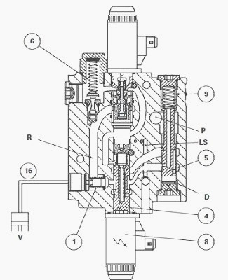
When the Move Up solenoid valve (8) is activated, the control spool (4)
is moved upwards. The LS pressure information acting on the upper face
of the flow rate regulating spool (5) (spring (9) side) moves the spool
downwards thus directing the flow to the control spool and the
non-return valve (1).
The movement of the flow regulating spool valve is dampened by the volume of oil present in chamber D. As soon as the pressure on the valve (1) is greater than that in the rams, the lifting arms rise.
The LS line communicates with the outlet line (16) to the lift rams thus informing the variable displacement pump regulator.
If the pressure in the rams is too high (shocks received by
the lifting arm), the valve (6) opens and the excess pressure is
directed to the return.
Down position
When the solenoid valve (7) is activated to lower the lifting arm, the
spool valve assembly (2) allows the oil coming from the rams to flow
into the return.
The LS pressure information is transmitted to the side of the flow rate regulating spool (5) (spring (9) side) and to the variable displacement pump.
________________________________________________________________________________
________________________________________________________________________________________
 SPECS
SPECS LOADERS
 MAINTENANCE
 PROBLEMS
________________________________________________________________________________________
 MF 1523
 MF 1531
 MF 135
 MF 1547
 MF 1635
________________________________________________________________________________________
________________________________________________________________________________________
 231
231 231S
231S 235
235 240
240 241
241________________________________________________________________________________________
 255
255 265
265 274
274 285
285 375
375________________________________________________________________________________________
________________________________________________________________________________________
 916X Loader
 921X Loader
 926X Loader
 931X Loader
 936X Loader
________________________________________________________________________________________
 941X Loader
 946X Loader
 951X Loader
 956X Loader
 988 Loader
________________________________________________________________________________________
 1655
1655 GS1705
 1742
1742 2635
2635 4608
4608________________________________________________________________________________________
 1080
1080 1100
1100 2615
2615 3050
3050 3060
3060________________________________________________________________________________________
 4708
4708 5455
5455 5450
5450 5610
5610 5613
5613________________________________________________________________________________________
 DL95 Loader
 DL100 Loader
 DL120 Loader
 DL125 Loader
 DL130 Loader
________________________________________________________________________________________
 DL135 Loader
 DL250 Loader
 DL260 Loader
 L90 Loader
 L100 Loader
________________________________________________________________________________________
 6499
6499 7480
7480 7618
7618 7726
7726 1533
1533________________________________________________________________________________________
 2604H
2604H 2607H
2607H 4455
4455 4610M
4610M 4710
4710________________________________________________________________________________________
 L105E Loader
 L210 Loader
 1014 Loader
 1016 Loader
 1462 Loader
________________________________________________________________________________________
 1525 Loader
 1530 Loader
 232 Loader
 838 Loader
 848 Loader
________________________________________________________________________________________
 5712SL
 6713
6713 6715S
6715S 7475
7475 7615
7615________________________________________________________________________________________
 7716
7716 7724
7724 8240
8240 8650
8650 8732
8732________________________________________________________________________________________
 246 Loader
 1036 Loader
 1038 Loader
 1080 Loader
 856 Loader