
________________________________________________________________________________
Massey Ferguson 8140, 8160 heavy gearbox 32 speeds
Massey Ferguson 8140, 8160 tractor heavy gearbox comprises 32 forward speeds and 32 reverse.
The transfer shafts and output shafts are supported by tapered roller bearings and are drilled as necessary to pressure-lubricate the bearings, the idler gears and the Hare or Tortoise synchronization system.
The lay shaft is supported at the front by a cylindrical roller bearing and at the rear, by two tapered roller bearings. The main gearbox comprises four synchronized gears.
An idler gear on the output shaft positively connected via a double cone synchromesh doubles the four synchronized gears, to give the eight basic speeds.
All pinions are helically cut and in constant engagement. The drive
shaft of the direct-drive clutch traverses the layshaft. The input unit
assembly located at the front provides four input ratios into the main
box.
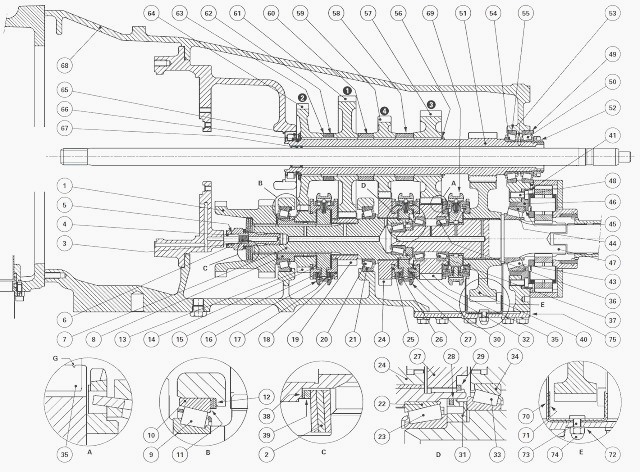
MF 8140, 8160 heavy gearbox 32+32 Components
(1) Input gear (2) Belleville washers (3) Special screw (4) Lube tube
(5) Snap ring (6) Spring (7) Transfer shaft (8) Bush (9) Bearing cone
(10) Bearing cup (11) Shim(s) (12) Thick shim (13) Driving pinion (2nd)
(14) Synchromesh cone (2nd) (15) Synchro ring (2nd) (16) Synchro (1st -
2nd) (17) Synchro ring (1st) (18) Synchromesh cone (1st ) (19) Driving
pinion (1st ) (20) Bearing cone (21) Bearing cup (22) Bearing cup (23)
Bearing cone (24) Driving pinion (4th) (25) Synchromesh cone (4th) (26)
Synchromesh ring (4th) (27) Synchro (3rd - 4th) (28) Seal ring (29) Snap
ring (30) Synchromesh ring (3rd) (31) Special washer (32) Synchromesh
cone (3rd) (33) Bearing cone (34) Bearing cup (35) Driving pinion (3rd)
(Hare) (36) Bearing cup (37) Bearing cone (38) Shim(s) (39) Thick shim
(40) Tortoise gear (41) Centering pin (43) Bearing cone (44) Bearing cup
(45) Shim(s) (46) Rear bearing (47) Output shaft (48) Screw (49) Bearing
cup (50) Bearing cone (51) Layshaft (52) Nut (53) Shim (54) Bearing cone
(55) Bearing cup (56) Circlip (57) Driven pinion (3rd) (58) Spacer (59)
Driven pinion (4th) (60) Spacer (61) Driven pinion (1st) (62) Spacer
(63) Shim(s) (64) Driven pinion (2nd) (65) Washer (66) Snap ring (67)
Needle roller bearings (68) Gearbox housing (69) H/T synchromesh (double
cone)
The Massey Ferguson 8160, 8140 gearbox drive is provided by input gear
(1) integral with transfer shaft (7). The two hubs of synchromesh gears
(16) and (27), as well as gear (1) are hard-mounted to transfer shaft
(7) by splines.
First gear (19) and fourth gear (24) are idler gears on shaft (7). Second gear (13) is an idler gear on bush (8), which is hard-mounted to shaft (7) by splines.
Third gear 3rd (35) is installed on tapered roller bearings. All the
pinions on layshaft (51) are splined to and rotate with the latter. The
gear teeth on shaft (51) mesh with tortoise gear (40) which idles on the
output shaft.
Low range (Tortoise)
A synchronized gear is engaged by moving of one of the slides of
synchromesh gears (16) or (27) for engage transfer shaft (7) in one of
the four idling pinions.
Irrespective of the speed selected, the movement is transmitted to layshaft (51).
Output shaft (47) is driven by the gear teeth machined on
the layshaft intermeshing
with tortoise gear (40), engaged to output shaft (47), by moving the
slide of synchromesh gear (69) rearwards.
High range (Hare)
This range is selected by forward movement of the slide of synchromesh
gear (69), which establishes a direct drive between third gear (35) and
output shaft (47).
Consequently in 3rd gear, layshaft (51) is passive.
The other gears are
obtained by moving the slides of synchros (16) or (27) as for the Low
range.
Lubrication
The lube oil is supplied from tube (4) connected to the input unit. It
circulates in a series of axial channels, one of which crosses the
transfer shaft while the other is
blind, machined in the output shaft.
Radial channels feed the various pinions, the bearings and the Hare or Tortoise synchromesh. Needle roller bearings (67) are lubricated by an oil film circulating between the direct-drive shaft and the layshaft.
The shaft-end bearings
on shaft (51) are lubricated
by an additional oil flow from the drive bearing of the hydraulic pumps
located on the rear-axle intermediate housing, via radial ports drilled
respectively in shim (53)
and the shaft.
Synchromesh gears single cone
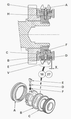
MF 8160, 8140 gearbox synchromesh gears single cone
Locking position
Axial displacement of slide A presses synchronization brake B against
friction cone C through the action of balls D and pressure system E.
The
speed difference
existing between the parts being coupled causes a radial rotation
limited by pressure system E resulting in turn in a pressure causing the
chamfered teeth of
synchronization brake B to move against slide A, opposing all relative
movement of the latter.
The pressure exerted by slide A and the angular difference of
synchronization brake B create an axial pressure between the friction
cones of synchronization brake
B, and cone C, due to the chamfers of the gear teeth; this axial
pressure establishes synchronism by progressive reduction of the speed
difference of the parts to
connect.
Once synchronism is established, the persistent pressure exerted by
slide A against synchronization brake B returns the latter backwards
until the teeth of slide A
are opposite the recess in synchronization brake B.
At this moment, the
resistance applied till this point preventing movement of slide A during
gear changing is
overcome and slide A can thus mesh without noise in the gear teeth of
cone C on the gear to be brought into drive.
The rigid connection between the shaft and the gear is now established,
and the gears change. If during gear-changing both gears end up
tooth-on-tooth, the
chamfers machined on the tooth flanks displace the arriving gear until
each tooth is opposite a recess.
Neutral position
Slide A is in the central position. The balls are pushed back into the
groove at V on slide A by pressure springs F.
The pinions are free to
turn on the shaft. In this
neutral position, slide A is locked by three balls G maintained by
springs H.
Overhaul
In the event of removal of the synchromesh gears, check the wear of
synchronization brakes B.
Place Cone C on a flat surface and position brake B in abutment by rotating it a few turns under finger pressure.
Measure dimension X at several points using a set of feeler gauges: if a value of less than
0.8 mm is found, check the cone and install a new brake B.
Value of dimension X with brake and new synchromesh cone
- synchro (1st - 2nd) (16): 0.9 to 1.5 mm
- synchro (3rd - 4th) (27): 0.9 to 1.5 mm
Synchromesh gears double cone
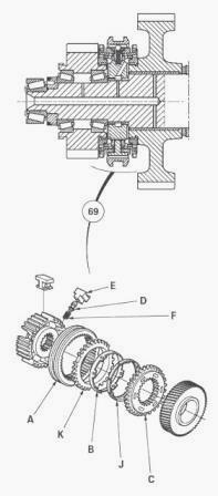
MF 8140, 8160 gerbox synchromesh gears double cone
Locking position
Axial displacement of slide A provides a thrust against ring K, which in
turn bears on synchronization brake B, pushing it towards Cone J through
the action of balls
D, spring F and pressure system E.
When the corresponding pinions are at the required speed, the slide
meshes with the coupling flange C of the candidate gear.
Locking of the synchromesh in position (and the neutral position) employ
the same principle as for single cone synchromesh gears.
Advantages of the double cone synchromesh
- better reliability
- increased stress strength
Overhaul (double cone)
- If needing to disassemble synchromesh (69), check the wear on
synchronization brakes B.
- Proceed by stacking coupling flange C, cone J, synchronization brake B
and ring K.
- Position brake B correctly by alternately rotating it through a few
turns and applying finger pressure.
- Using a set of feeler gauges, measure dimension at three equidistant
points. Take the average of\ the three readings.
Value of dimension
- on a new synchromesh gear, dimension must be 1.6 mm minimum;
- after operation, if this dimension is less than or equal to 0.60 -
0.80 mm, replace the synchronization brake B.
- Repeat the measurement of using the same process.
- If dimension remains incorrect, also replace ring K and cone J or the
complete synchromesh if required.
________________________________________________________________________________
________________________________________________________________________________________
 SPECS
SPECS LOADERS
 MAINTENANCE
 PROBLEMS
________________________________________________________________________________________
 MF 1523
 MF 1531
 MF 135
 MF 1547
 MF 1635
________________________________________________________________________________________
________________________________________________________________________________________
 231
231 231S
231S 235
235 240
240 241
241________________________________________________________________________________________
 255
255 265
265 274
274 285
285 375
375________________________________________________________________________________________
________________________________________________________________________________________
 916X Loader
 921X Loader
 926X Loader
 931X Loader
 936X Loader
________________________________________________________________________________________
 941X Loader
 946X Loader
 951X Loader
 956X Loader
 988 Loader
________________________________________________________________________________________
 1655
1655 GS1705
 1742
1742 2635
2635 4608
4608________________________________________________________________________________________
 1080
1080 1100
1100 2615
2615 3050
3050 3060
3060________________________________________________________________________________________
 4708
4708 5455
5455 5450
5450 5610
5610 5613
5613________________________________________________________________________________________
 DL95 Loader
 DL100 Loader
 DL120 Loader
 DL125 Loader
 DL130 Loader
________________________________________________________________________________________
 DL135 Loader
 DL250 Loader
 DL260 Loader
 L90 Loader
 L100 Loader
________________________________________________________________________________________
 6499
6499 7480
7480 7618
7618 7726
7726 1533
1533________________________________________________________________________________________
 2604H
2604H 2607H
2607H 4455
4455 4610M
4610M 4710
4710________________________________________________________________________________________
 L105E Loader
 L210 Loader
 1014 Loader
 1016 Loader
 1462 Loader
________________________________________________________________________________________
 1525 Loader
 1530 Loader
 232 Loader
 838 Loader
 848 Loader
________________________________________________________________________________________
 5712SL
 6713
6713 6715S
6715S 7475
7475 7615
7615________________________________________________________________________________________
 7716
7716 7724
7724 8240
8240 8650
8650 8732
8732________________________________________________________________________________________
 246 Loader
 1036 Loader
 1038 Loader
 1080 Loader
 856 Loader