
________________________________________________________________________________
Massey Ferguson 8737, 8730 Dyna VT transmission PTO - Installing the set of discs on the disc carrier

MF 8737, 8730 PTO clutch
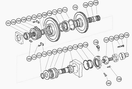
Massey Ferguson 8737, 8730 Rear PTO drive
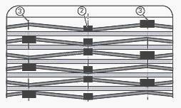
Start with an external blade. Next alternate with an internal blade
(11). Each internal blade (11) should be fitted in respect to the narrow
slot (pos. 2) while the wide slot (pos. 3) should be positioned either
side alternately.
Total number of discs: 7 external discs (12) and 6 internal discs (11).
Fit the disc carrier (6) together with the set of Belleville washers
(9). Fit the compression tool. Compress the MF 8737, 8730 clutch. Fit
the locking half-rings (30).
If the locking half-rings are chamfered on just one side, the chamfered side must face the disc carrier (6). If the disc carrier (6) does not fit into place, fit it without the set of discs (10) and mark the teeth.
Push the set of discs home, ensuring it is correctly centred. Measure the distance (uncoupling clearance) using laminated shims. Specified values: 1.75 to 3.50 mm.
If the minimum distance of 1.75 mm is not obtained, the discs are wrapped. Fit a new set of discs (10). Smear the thread of the nozzle (29) with plastic binder.
Tighten the nozzle (29) to a torque of:25 Nm. If necessary, fit the bearing (28) to its stop with its closed part facing upwards into the interior of the clutch cover (3). Fit the bearing (2) up against the clutch cover (3).
Adjust the position of the external discs (12) and fit the clutch cover (3) to its stop. Fit compensating shims (1) on the bearing (2). Measure and note the distance between the mating faces. For example: 178.6 mm.
The distance between the flange face and the mating face of the journal is written in white on the top part of the rear axle housing. Example: 178.71.
The distance between the journal of the bearing (2) and the flange face of the housing cover should be less than 0.1 to 0.2 mm, as the written value indicates. This means that the journal clearance must be 0.1 to 0.2 mm.
If not, correct it with compensating shims (1). The distance between the flange face and the mating face of the journal of the lower shaft is written in white on the lower part of the rear axle housing. Example: 148.75.
This value is not necessary in case of repair, because a dial gauge must be used to measure the bearing clearance. Check the bearing clearance of the lower shaft (120).
Fit the compensating shims (1) in the upper bore. Smear 4 new O’rings
with miscible grease and fit them at the position of the oil pressure
pipes.
Clean the housing mating face. Check the 2 locating pins are fitted
correctly. Smear the mating face with sealing product. Carefully raise
the housing cover and fit it on the rear axle housing. Tighten the M18
screws and nuts to a torque of: 400 Nm.
If necessary: Smear the outside of a new shaft sealing ring (126) with a
thin layer of sealing product (ref. X 903.051.711), and insert it until
it comes into light contact with the cover (128), the seal lips turned
towards the oil chamber. Depth approximately 5 mm. Fill the lip seals
2/3 full with miscible grease.
Fit the corresponding compensating shims (124). Smear new O’rings (127)
with miscible grease and fit them in the groove of the cover (128).
Smear the thread of the screws (129) with plastic binder (ref. X
903.050.084) and tighten. Rotate the shaft (120) 10 times. Fit a dial
gauge. Push in the shaft (120) once and note the clearance value J2.
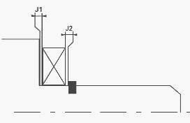
Rotate the shaft (120) 10 times. Fit a dial gauge. Pull once on the
shaft (120) and note the clearance value J1.
Total clearance J = J1+ J2. 0.02 mm < J < 0.07 mm. If not, correct it
with compensating shims (124). PTO end-fitting with 6 x 1’ 3/8" splines.
Also compatible:
PTO end-fitting with 21 x 1’ 3/8" splines
PTO end-fitting with 6 x 1’ 3/4" splines
PTO end-fitting with 20 x 1’ 3/4" splines
The PTO end-fitting has 4 drive holes for the PTO sensor. Fit the
end-fitting (137). Fit the spacer (132). Lock the end-fitting (137 with
a screw M16 (for easier assembly).
Tighten the nuts (134) (M0-10) to a torque of: 69 Nm. Top up the transmission oil level.
________________________________________________________________________________
________________________________________________________________________________________
 SPECS
SPECS LOADERS
 MAINTENANCE
 PROBLEMS
________________________________________________________________________________________
 MF 1523
 MF 1531
 MF 135
 MF 1547
 MF 1635
________________________________________________________________________________________
________________________________________________________________________________________
 231
231 231S
231S 235
235 240
240 241
241________________________________________________________________________________________
 255
255 265
265 274
274 285
285 375
375________________________________________________________________________________________
________________________________________________________________________________________
 916X Loader
 921X Loader
 926X Loader
 931X Loader
 936X Loader
________________________________________________________________________________________
 941X Loader
 946X Loader
 951X Loader
 956X Loader
 988 Loader
________________________________________________________________________________________
 1655
1655 GS1705
 1742
1742 2635
2635 4608
4608________________________________________________________________________________________
 1080
1080 1100
1100 2615
2615 3050
3050 3060
3060________________________________________________________________________________________
 4708
4708 5455
5455 5450
5450 5610
5610 5613
5613________________________________________________________________________________________
 DL95 Loader
 DL100 Loader
 DL120 Loader
 DL125 Loader
 DL130 Loader
________________________________________________________________________________________
 DL135 Loader
 DL250 Loader
 DL260 Loader
 L90 Loader
 L100 Loader
________________________________________________________________________________________
 6499
6499 7480
7480 7618
7618 7726
7726 1533
1533________________________________________________________________________________________
 2604H
2604H 2607H
2607H 4455
4455 4610M
4610M 4710
4710________________________________________________________________________________________
 L105E Loader
 L210 Loader
 1014 Loader
 1016 Loader
 1462 Loader
________________________________________________________________________________________
 1525 Loader
 1530 Loader
 232 Loader
 838 Loader
 848 Loader
________________________________________________________________________________________
 5712SL
 6713
6713 6715S
6715S 7475
7475 7615
7615________________________________________________________________________________________
 7716
7716 7724
7724 8240
8240 8650
8650 8732
8732________________________________________________________________________________________
 246 Loader
 1036 Loader
 1038 Loader
 1080 Loader
 856 Loader