
________________________________________________________________________________
Orbitrol - Hydrostatic steering
The steering unit (Orbitrol) is attached to the pedal console which is
housed at the centre of the front firewall in the cab. Its
characteristics are written on a plate riveted to the lower part of the
spool valve.
The Massey Ferguson 5445, 5435, 5425 Tractors hydraulic steering system
has no mechanical connection between the steering wheel and steering
ram.
The system comprises the following main
components:
- a pressurised oil supply from the low flow rate stage of the hydraulic
pump,
- a hydrostatic (Orbitrol) steering unit fitted in parallel,
- a central double acting ram.
MF 5445, 5435, 5425 Tractors hydraulic
steering operation
The spool valve receives a priority supply from the low flow rate
circuit. When the steering wheel is turned, the necessary flow of oil is
directed to the corresponding side of the steering ram.
Excess flow rate not required by the ram is directed via return ports to
the 17 bar valve located on the left-hand hydraulic cover.
In case of an engine breakdown or hydraulic failure, the spool valve
acts as a hand-operated pump so that the steering can be controlled.
Operating in this way requires greater effort to be applied to the
steering wheel.
Description of the hydraulic steering
unit (Orbitrol)
The Orbitrol comprises a selector spool valve, a spring centred supply
sleeve and a drive shaft linked to the steering column.
It has four hydraulic ports:
- pressure;
- return to the 17 bar valve;
- two supplies to the steering ram.
The circuit is protected by a safety valve, two shock valves and two
suction valves.
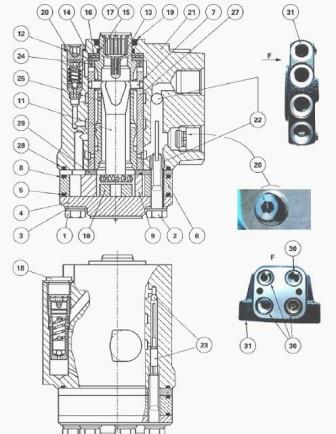
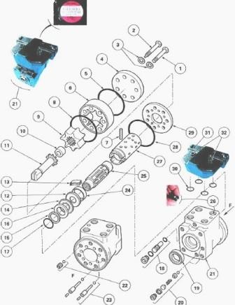
Fig.19/20. Parts list
(1) Screw (2) Screw (3) Seal (4) Closing plate (5) O’ring (6) Stator (7)
Cotter pin (8) O’ring (9) Rotor (10) Spacer (11) Link shaft (12) Washer
(13) Centring springs (14) Needle bearing (15) Ring (16) Washer (17)
O’ring (18) Relief valve (19) Seal (20) Shock valve (21) Orbitol
steering unit (22) Non-return valve (23) Suction valves (24) Ring (25)
Spool valve (26) Non-return valve (27) Sleeve (28) O’ring (29)
Distributor plate (30) O’rings (31) Manifold (32) Screw
Layout of the main components of the
Massey Ferguson 5435, 5445, 5425 Tractor front axle and hydraulic ports
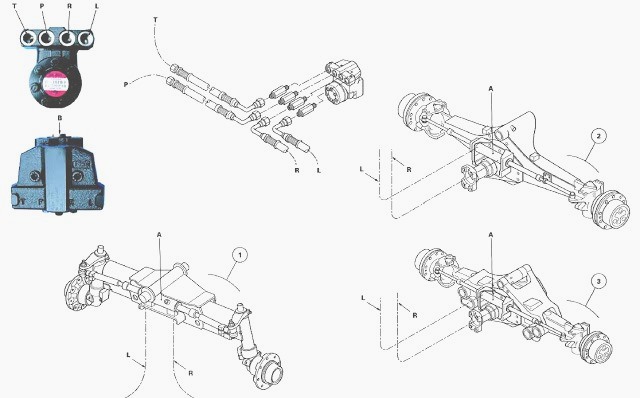
Fig.21,22. Front axle system / Hydraulic ports
1 - 2RM axle beam, 2 - 4WD fixed front axle, 3 - 4WD suspended front
axle, A - Steering ram, B - Location of steering column, LM - Mechanical
links, L - Supply to left-hand union of the steering ram, P - Low flow
rate - low pressure supply from the hydraulic pump (right-hand cover), R
- Supply to right-hand union of the steering ram, T - Supply to the 17
bar valve housed in the left-hand hydraulic cover
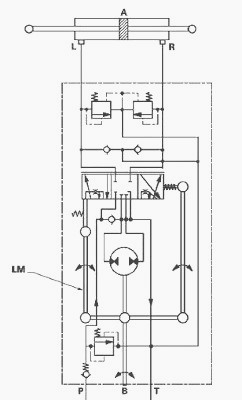
Neutral position (engine running)
In this position the spool valve (25) is centred in relation to the
sleeve (27) by the springs (13). The channels (P1), (L) and (R) are not
supplied. The oil coming from port (P) passes directly via hose (T) to
supply the 17 bar valve.
The circuit is open centre. Two shock valves (20) and two suction valves
(23) are located in ports (L) and (R) of the spool valve. The shock
valves (20) protect the circuit between the steering ram and the spool
valve from overpressure caused by mechanical shocks to the front wheels.
The suction valves (23) allow the oil released by the shock valves (20)
to pass from the right-hand channel to the left-hand channel or vice
versa depending on the movement of the piston inside the steering ram.
MF 5445, 5435, 5425 Steering on lock position
(engine running)
Action on the steering wheel (to the left or right) produces an angular
displacement of the spool valve (25) in relation to the sleeve (27). The
flow coming from the pump is directed to the metering device (stator (6)
and rotor (9)).
The rotor (9) is rotated and directs back into the cylinder a quantity
of oil proportional to the rotational angle. The rotor (9) turns
proportionally to the steering wheel.
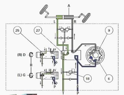
Fig.23
For example:
Let us suppose that the steering wheel is turned by 5°. An angular
displacement of 5° of the spool valve (25) is produced in relation to
the sleeve (27). The rotor (9) is driven in rotation as long as it is
supplied.
It drives with it the link shaft (11) and sleeve (27). When these have
turned 5°, the spool valve (25) and sleeve (27) are centred again, by
springs (13). The rotor ceases to be supplied and stops.
This same reasoning applies to greater angles. The quantity of oil
delivered by the steering unit to the cylinder (A) is therefore
proportional to the rotational angle of the steering wheel.
The spool valve (25) allows, whether steering lock is applied to the
left or right, to direct oil fed by the metering device (stator (6) and
rotor (9)) to port (L) or (R).
During rotation, the sleeve (27) ensures the synchronous communication
of the metering device cavities with the circuit from the pump, on the
one-hand, and the circuit to the cylinder (A), on the other hand. A
non-return valve (26) is screwed into the supply port of the spool
valve.
This one-way valve stops excessive pressure or blows received by the
front wheels from being transmitted to the pump whenever steering lock
is applied.
If the pressure in the circuit is too high, the relief valve (18)
located in the spool valve is activated: the excess pressure is then
directed to the channel (T).
Massey Ferguson MF 5435, 5445, 5425 Tractor
Manual steering (engine stopped)
When the pump is no longer operating or the available pressure is too
low, the metering device is no longer hydraulically driven. It is no
longer power assisted. In this case, action on the steering wheel
compresses the centring springs (13).
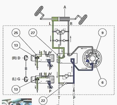
Fig.24
The angular clearance between the pin (7) and the sleeve (27) is reduced
to zero resulting in mechanical rotation of the metering device (stator
(6) and rotor (9)). The steering unit then operates in the same way as a
hand pump.
The oil returning from steering ram (A) passes through the non-return
valve (22) and supplies the metering device.
The pressure generated is proportional to the torque applied to the
steering wheel. The effort therefore required to turn the wheel in order
to steer the tractor is much greater.
________________________________________________________________________________
________________________________________________________________________________________
 SPECS
SPECS LOADERS
 MAINTENANCE
 PROBLEMS
________________________________________________________________________________________
 MF 1523
 MF 1531
 MF 135
 MF 1547
 MF 1635
________________________________________________________________________________________
________________________________________________________________________________________
 231
231 231S
231S 235
235 240
240 241
241________________________________________________________________________________________
 255
255 265
265 274
274 285
285 375
375________________________________________________________________________________________
________________________________________________________________________________________
 916X Loader
 921X Loader
 926X Loader
 931X Loader
 936X Loader
________________________________________________________________________________________
 941X Loader
 946X Loader
 951X Loader
 956X Loader
 988 Loader
________________________________________________________________________________________
 1655
1655 GS1705
 1742
1742 2635
2635 4608
4608________________________________________________________________________________________
 1080
1080 1100
1100 2615
2615 3050
3050 3060
3060________________________________________________________________________________________
 4708
4708 5455
5455 5450
5450 5610
5610 5613
5613________________________________________________________________________________________
 DL95 Loader
 DL100 Loader
 DL120 Loader
 DL125 Loader
 DL130 Loader
________________________________________________________________________________________
 DL135 Loader
 DL250 Loader
 DL260 Loader
 L90 Loader
 L100 Loader
________________________________________________________________________________________
 6499
6499 7480
7480 7618
7618 7726
7726 1533
1533________________________________________________________________________________________
 2604H
2604H 2607H
2607H 4455
4455 4610M
4610M 4710
4710________________________________________________________________________________________
 L105E Loader
 L210 Loader
 1014 Loader
 1016 Loader
 1462 Loader
________________________________________________________________________________________
 1525 Loader
 1530 Loader
 232 Loader
 838 Loader
 848 Loader
________________________________________________________________________________________
 5712SL
 6713
6713 6715S
6715S 7475
7475 7615
7615________________________________________________________________________________________
 7716
7716 7724
7724 8240
8240 8650
8650 8732
8732________________________________________________________________________________________
 246 Loader
 1036 Loader
 1038 Loader
 1080 Loader
 856 Loader