________________________________________________________________________________
Kubota BX1870, BX2370, BX2670 - Transmission Service
Kubota BX1870, BX2370, BX2670 Hydrostatic
Transmission - Checking And Adjusting
Adjustment of HST Neutral Position

1 - Range Gear Shift Lever, 2 - Front Wheel Drive, 3 - Speed Control
Pedal, 4 - Neutral Adjust Lever, 5 - Locking Screw, 6 - Screw Driver, A
- 4WD OFF Position, B - Hi Position
Start the engine. Keep the engine at the maximum revolution. Shift the
range shift lever (1) to “Hi” position (B). Loosen the locking screw
(5). When adjusting the HST neutral position, loosen the locking screw
approximately 2 turns counterclockwise not to drop the nut inside. Make
sure 4WD lever is set to 2WD before making adjustment. Forward to
Neutral Position - Depress the speed control pedal (3) to “Forward”
speed position, and release the foot from the speed control pedal (3).
Check that the rear axle (or the wheel) stops rotating. If the rear axle
(or the wheel) does not stop rotating, move the position of the locking
screw (5) to the machine front side to stop rotating. Reverse to Neutral
Position - Depress the speed control pedal (3) to “Reverse” speed
position, and release the foot from the speed control pedal (3). Check
the rear axle (or the wheel) stops rotating. If the rear axle (or the
wheel) does not stop rotating, adjust the locking screw (5) to stop
rotating. After adjusting the neutral position, tighten the lock screw
(5) securely.
Charge Relief Pressure
Remove the plug (R 1/4) from the front cover, then install the adaptor
(R 1/4) and pressure gauge. Set the range gear shift lever to “Neutral”
position. Start the engine and run it at the maximum speed. Read the
pressure gauge to measure the charge relief pressure. If the measurement
is not within the factory specifications, check the charge relief valve
and related hydraulic components. Charge relief pressure (Oil
temperature at 50C) - 0.55 to 0.75 MPa (80 to 100 psi).
PTO Clutch Operating Pressure
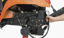
Lift the rear of the tractor and remove the left rear wheel. Remove the
plug (R 1/8), then install the adaptor (R 1/8), cable and pressure
gauge. Start the engine and set at maximum speed. Move the PTO clutch
lever to “Engaged” position, and measure the pressure. If the
measurement is not same as factory specifications, check the PTO relief
valve and related hydraulic components. PTO clutch operating pressure -
1.0 to 1.3 MPa (150 to 180 psi).
Kubota BX1870, BX2370, BX2670 - Hydrostatic
Transmission Service
Removing hydrostatic transmission case front
cover
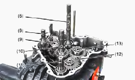
1. 4WD detent bolt, 2. Detent spring, 3. Detent ball, 4. Transaxle case
front cover, 5. Circlip, 6. HST pump shaft (PTO shaft), 7. Front cover
mounting bolt, 8. Front wheel drive shaft, 9. Spiral bevel pinion shaft,
10. HST motor shaft, 11. Mid-PTO shaft, 12. Mid-PTO idle gear shaft, 13.
PTO select shaft
Before removing the transaxle case front cover (4), remove the 4WD
detent bolt (1), the detent spring (2) and the detent ball (3) from the
transaxle case front cover (4). Remove the circlip (5) from the
hydrostatic transmission pump shaft (PTO shaft) (6) and the HST motor
shaft securely. Remove the transaxle case front cover mounting bolts
(7). Remove the transaxle case front cover (4) as an unit. Apply liquid
gasket to the joint surface of the transaxle case to the front cover.
Removing hydraulic pump assembly
Remove the hydraulic pump assembly mounting bolt. Remove the hydraulic
pump assembly as an unit from the transaxle case. Apply transmission oil
to the O-rings. Since the mounting bolt is installed through the
hydraulic pump to the transaxle case, bind the sealing tape to the
mounting bolt securely.
Removing rear PTO cover assembly
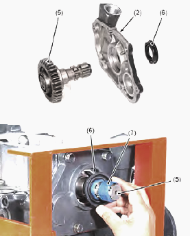
1 - Bolt, 2 - Rear PTO cover, 3 - Bearing, 4 - 11T PTO select shaft, 5 -
Rear PTO shaft, 6 - Oil seal, 7 - Vinyl tape
Remove the rear PTO cover mounting bolts. Remove the rear PTO cover.
Remove the rear PTO shaft from the rear PTO cover. Pull the 11T PTO
select shaft with the bearing approximately the bearing thickness. Apply
liquid gasket to the joint surface of transaxle case to the rear PTO
cover. Bind the vinyl tape to the rear PTO shaft not to damage the oil
seal.
Kubota BX1870, BX2370, BX2670 - Removing PTO
clutch assembly
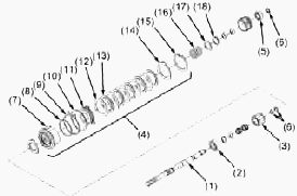
1 - Pump shaft (PTO clutch shaft), 2 - Bearing, 3 - Clutch gear, 4 -
Clutch pack, 5 - Bearing, 6 - Seal ring, 7 - Clutch case, 8 - O-ring, 9
- Brake disc, 10 - Brake plate, 11 - Clutch piston, 12 - Separate plate,
13 - Disc plate, 14 - Backing plate, 15 - Internal circlip, 16 - Brake
spring, 17 - Washer, 18 - External circlip, 19 - Clutch spring
compressor
Remove the bearing (2). Remove the external circlip and the clutch gear
(3). Remove the seal rings (6). Remove the bearing (5). Remove the
external circlip (18) using a clutch spring compressor. Disassembling
the clutch pack inner parts as show in the figure. Change the seal rings
(6) with a new one.
Check and high pressure relief valve checking
Check and high pressure relief valve (reverse) has a pin hole. Pin hole
(Factory specification) - 1.5 mm / 0.059 in. Check the check and high
pressure relief valve for scratches and damage. Check the spring for
breakage and wear. If anything are unusual, replace the check and high
pressure relief valve as complete assembly.
Checking cylinder block assembly
Do not interchange the pistons between the pump cylinder block and the
motor cylinder block. Pistons and cylinder blocks are matched. Check the
cylinder blocks and the pistons for scratches and wear. If there are
scratch or worn, replace the cylinder block assembly. Check the pistons
for their free movement in the cylinder block bores. If the piston or
the cylinder block is scored, replace the cylinder block assembly. Check
the polished face of the cylinder block for scoring. If it is scored,
replace the cylinder block assembly.
Kubota BX1870, BX2370, BX2670 Transmission
Problems
Vibration and Noise
Oil level is too low - Check oil level or fill oil to proper level.
Speed control pedal linkage defective - Repair linkage.
Charge pressure is too low - Replace oil filter cartridge. Check charge
pressure. Inspect or flush charge relief valve.
Check and high pressure relief valve doesn't move smoothly -
Inspect/replace check and high pressure relief valve.
Defective component parts - Replace hydrostatic transmission assembly.
Loss of Power
Low oil level - Add oil in hydrostatic transmission.
Low charge pressure - Replace oil filter cartridge. Checking charge
pressure. Repair the charge relief valve.
Component parts are worn - Check and repair hydrostatic transmission
components.
Transmission Oil Overheats
Transmission oil level is low - Fill transmission oil level up to proper
level.
Radiator net clogged - Clean radiator net.
Excessive machine load - Reduce machine load.
Improper charge pressure - Check high relief pressure. Change
transmission oil filter cartridge. Inspect and change the relief valve.
Noise from Transmission
Transmission oil insufficient - Refill.
Gear worn or broken - Check and replace.
Bearings worn - Change defective parts.
Gear Slip Out of Mesh
Shift fork spring tension insufficient - Replace defective parts.
Shift fork or shifter worn - Change damage parts.
Shift fork bent - Replace.
Differential Lock Can Not Be Set
Differential lock shift fork damaged - Replace.
Differential lock shifter mounting pin damaged - Replace.
Differential lock pin damaged - Replace.
PTO Clutch Operating Pressure is Low
Transmission oil improper or insufficient - Replenish or change.
Relief valve malfunctioning - Check or replace.
Kubota BX1870, BX2370, BX2670 Transmission -
Servicing Specifications
| Item | Factory Specification | Allowable Limit |
| Charge Relief Valve Setting Pressure | 0.55 to 0.75 MPa (80 to 100 psi) | - |
| High Pressure Relief Valve (F/R) Setting Pressure | 20.1 to 21.1 MPa (2920 to 3060 psi) | - |
| PTO Clutch Operating Pressure | 1.0 to 1.3 MPa (150 to 180 psi) | - |
| PTO Clutch Disc Thickness | 1.50 to 1.70 mm (0.0591 to 0.0669 in) | 1.35 mm (0.0531 in) |
| Separate Plate Thickness | 0.945 to 1.055 mm (0.0372 to 0.0415 in) | 0.80 mm (0.031 in) |
| Back Plate Thickness | 1.9 to 2.1 mm (0.075 to 0.082 in) | 1.85 mm (0.0728 in) |
| Clutch Piston Flatness | - | 0.15 mm (0.0059 in) |
| Pressure Plate and Steel Plate Flatness | - | 0.20 mm (0.0079 in) |
| Clutch Spring Free Length | 38.5 mm (1.52 in) | 34.5 mm (1.36 in) |
| PTO Brake Disc Thickness | 2.90 to 3.10 mm (0.115 to 0.122 in) | 2.70 mm (0.11 in) |
| PTO Brake Plate Thickness | 1.9 to 2.1 mm (0.075 to 0.082 in) | 1.85 mm (0.073 in) |
| Differential Case / Differential Side Gear Clearance | 0.05 to 0.151 mm (0.00197 to 0.00594) | 0.30 mm (0.012 in) |
| Differential Case I.D. | 38.0 to 38.062 mm (1.4961 to 1.4985 in) | - |
| Differential Side Gear O.D. | 37.911 to 37.95 mm (1.4926 to 1.4940 in) | - |
| Differential Pinion Shaft / Differential Pinion Clearance | 0.08 to 0.122 mm (0.00315 to 0.0048 in) | 0.30 mm (0.012 in) |
| Differential Pinion I.D. | 20.06 to 20.08 mm (0.78977 to 0.7906 in) | - |
| Differential Pinion Shaft O.D. | 19.96 to 19.98 mm (0.78579 to 0.7866 in) | - |
| Differential Pinion to Differential Side Gear Backlash | 0.15 to 0.30 mm (0.0059 to 0.011 in) | 0.40 mm (0.016 in) |
| Spiral Bevel Pinion Shaft / Spiral Bevel Gear Backlash | 0.10 to 0.30 mm (0.0040 to 0.011 in) | - |
| Actuator and Bearing Holder Flatness | - | 0.30 mm (0.012 in) |
| Cam Plate and Ball Height | 22.89 to 22.99 mm (0.9012 to 0.9051 in) | 22.40 mm (0.8819 in) |
| Brake Disc Thickness | 3.30 to 3.50 mm (0.130 to 0.137 in) | 3.0 mm (0.12 in) |
| Friction Plate Thickness | 1.92 to 2.08 mm (0.0756 to 0.0818 in) | 1.52 mm (0.0598 in) |
Kubota BX1870, BX2370, BX2670 Hydrostatic Transmission - Tightening Torques
| Item | Tightening torque |
| Charge relief valve checking plug (R 1/4) | 30 to 44 Nm (22 to 32 lbf-ft) |
| Hexagon socket head plug (R 1/4) | 30 to 44 Nm (22 to 32 lbf-ft) |
| Check and high pressure valve screw | 25 to 29 Nm (18 to 21 lbf-ft) |
| PTO clutch operating pressure plug (R 1/8) | 13 to 21 Nm (9.4 to 15 lbf-ft) |
| ROPS mounting nut | 124 to 147 Nm (91.2 to 108 lbf-ft) |
| Fuel tank stay mounting bolt and nut | 48 to 55 Nm (36 to 41 lbf-ft) |
| Fender bracket mounting bolt and nut | 147 Nm (91.2 to 108 lbf-ft) |
| Rear wheel mounting screw | 109 to 129 Nm (80.3 to 95.4 lbf-ft) |
| Hitch plate mounting bolt and nut | 124 to 147 Nm (91.2 to 108 lbf-ft) |
| Transaxle assembly mounting screw (M12) | 63 to 72 Nm (47 to 53 lbf-ft) |
| Transaxle assembly mounting screw (M14) | 124 to 147 Nm (91.2 to 108 lbf-ft) |
| Rear coupling mounting screw (M8) | 24 to 27 Nm (18 to 20 lbf-ft) |
| Front coupling mounting screw (M8) | 24 to 27 Nm (18 to 20 lbf-ft) |
| Hydrostatic transmission fan mounting screw (M8) | 9.8 to 11 Nm (7.3 to 8.6 lbf-ft) |
| Hydraulic control lever mounting bolt and nut | 18 to 20 Nm (13 to 15 lbf-ft) |
| HST front cover mounting bolt and nut | 18 to 20 Nm (13 to 15 lbf-ft) |
| Check and High pressure relief valve plug | 59 to 78 Nm (44 to 57 lbf-ft) |
| Hydraulic cylinder mounting screw | 40 to 44 Nm (29 to 32 lbf-ft) |
| Transmission case front cover mounting bolt (M8) | 30 to 34 Nm (22 to 25 lbf-ft) |
| Hydraulic pump assembly mounting bolt (M6) | 7.9 to 8.8 Nm (5.8 to 6.5 lbf-ft) |
| Hydraulic pump assembly mounting bolt (M8) | 18 to 20 Nm (13 to 15 lbf-ft) |
| Rear PTO cover mounting bolt (M8) | 18 to 20 Nm (13 to 15 lbf-ft) |
| Rear axle case (RH) mounting bolt (M8) | 18 to 20 Nm (13 to 15 lbf-ft) |
| 66T final gear mounting screw | 61 to 70 Nm (45 to 52 lbf-ft) |
________________________________________________________________________________
________________________________________________________________________________________
________________________________________________________________________________________
| KUBOTA TRACTORS SPECIFICATIONS |
________________________________________________________________________________________
________________________________________________________________________________________
________________________________________________________________________________________
________________________________________________________________________________________
________________________________________________________________________________________
________________________________________________________________________________________
________________________________________________________________________________________
________________________________________________________________________________________
________________________________________________________________________________________
________________________________________________________________________________________
________________________________________________________________________________________
________________________________________________________________________________________
________________________________________________________________________________________
________________________________________________________________________________________
________________________________________________________________________________________
| KUBOTA ENGINES DATA AND SERVICE SPECS |
________________________________________________________________________________________
________________________________________________________________________________________
________________________________________________________________________________________
________________________________________________________________________________________
________________________________________________________________________________________
| KUBOTA FRONT END LOADERS |
________________________________________________________________________________________
________________________________________________________________________________________
________________________________________________________________________________________
________________________________________________________________________________________
________________________________________________________________________________________
________________________________________________________________________________________
________________________________________________________________________________________
________________________________________________________________________________________
________________________________________________________________________________________
________________________________________________________________________________________
________________________________________________________________________________________
________________________________________________________________________________________
| KUBOTA TRACTORS TROUBLESHOOTING | ||||
| L235 | L2501 | L2550 | L275 | L3110 |
| L3301 | L35 | L3710 | L3901 | L4310 |
| L5030 | M4700 | M5700 | M6040 | M6800 |
| M8200 | M8540 | M9000 | MX5100 | MX5200 |

 SPECIFICATIONS
 LOADERS
 ENGINES
 MAINTENANCE
 PROBLEMS
 B1241
B1241 B1600
B1600 B1700
B1700 B1750
B1750 B21 Backhoe
 B2150
B2150 B2301
B2301 B2320
B2320 B2530
B2530 B26 Backhoe
 B2601
B2601 B2650HSD
 B3030
B3030 B3350
B3350 B6000
B6000 B6100
B6100 B6200
B6200 B7000
B7000 B7001
B7001 B7100HST
 B7200
B7200 B7500
B7500 B7510
B7510 B7800
B7800 B8200HST
 BX1880
 BX2200
 BX2230
 BX2350
 BX2370
 BX23S
BX23S BX25 TLB
 BX2660
 BX2680
 F3680
F3680 L175
L175 L185
L185 L210
L210 L225
L225 L235
L235 L245
L245 L260
L260 L275
L275 L285
L285 L305
L305 GR2120
 L1501
L1501 L2350
L2350 L2550
L2550 L2800
L2800 L3010
L3010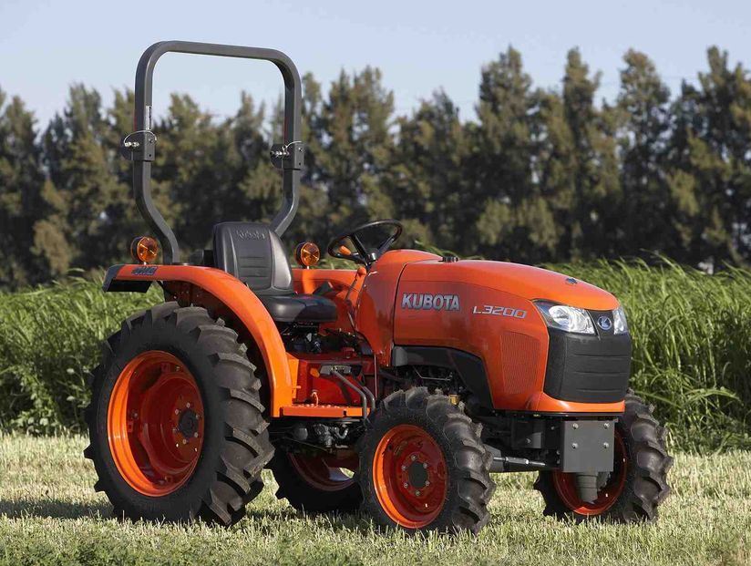 L3200HST
 L3301
L3301 L3560
L3560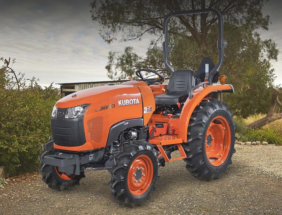 L3800
L3800 L4701
L4701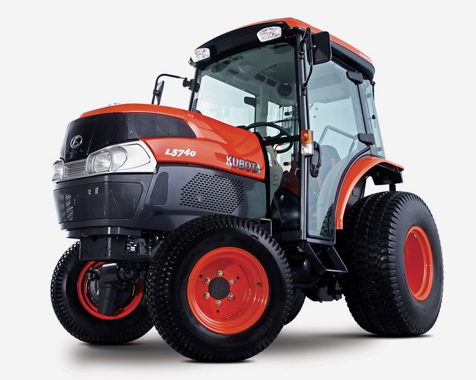 L5740
L5740 M5-091
 M5-111
 M6060
M6060 M7040
M7040 M9540
M9540 M9960
M9960 MX5100
 D662
D662 D722
D722 D750
D750 D782
D782 D850
D850 D902
D902 D905
D905 D950
D950 D1005
D1005 D1100
D1100 D1105
D1105 D1503
D1503 D1703
D1703 D1803
D1803 V1200
V1200 V1205
V1205 V1305
V1305 V1505
V1505 V2203
V2203 V2403
V2403 Z482
Z482 Z602
Z602 Z750
Z750 Z1100
Z1100 Z1300
Z1300 B1630
B1630 BF400
BF400 BF400G
 LA181
LA181 LA203
LA203 LA211
LA211 LA243
LA243 LA271
LA271 LA272
LA272 LA301
LA301 LA302
LA302 LA304
LA304 LA340
LA340 LA344
LA344 LA351
LA351 LA352
LA352 LA364
LA364 LA401
LA401 LA402
LA402 LA434
LA434 LA463
LA463 LA481
LA481 LA482
LA482 LA504
LA504 LA513
LA513 LA514
LA514 LA524
LA524 LA525
LA525 LA534
LA534 LA555
LA555 LA680
LA680 LA681
LA681 LA682
LA682 LA703
LA703 LA714
LA714 LA723
LA723 LA724
LA724 LA764
LA764 LA765
LA765 LA805
LA805 LA844
LA844 LA852
LA852 LA853
LA853 LA854
LA854 LA1002
 LA1055
 LA1065
 LA1153
 LA1154
 LA1251
 LA1301S
 LA1353
 LA1403
 LA1601S
 LA1854
 LA1944
 LA1953
 LA2253
 LM2605