________________________________________________________________________________
Kubota BX2200, BX2230, BX2350, BX22 - Transmission
Kubota BX2200, BX2230, BX2350, BX22 -
Hydrostatic Transmission
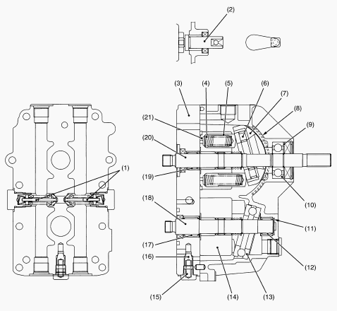
1 - Check and High Pressure Relief Valve, 2 - Trunnion Arm, 3 - Center
Unit, 4 - Piston Spring, 5 - Piston, 6 - Thrust Roller Bearing, 7 -
Swashplate, 8 - Cradle Bearing, 9 - Spacer, 10 - Ball Bearing, 11 -
Thrust Washer, 12 - Needle Bearing, 13 - Thrust Ball Bearing, 14 -
Cylinder Block (Motor), 15 - Charge Relief Spring, 16 - Charge Relief
Valve, 17 - Needle Bearing, 18 - Motor Shaft, 19 - Needle Bearing, 20 -
Pump Shaft, 21 - Cylinder Block (Pump)
Pump and Motor
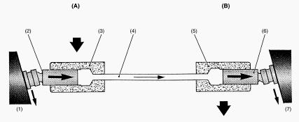
1 - Swashplate, 2 - Piston, 3 - Cylinder, 4 - Oil, 5 - Cylinder, 6 -
Piston, 7 - Swashplate, A - Pump, B - Motor
The hydrostatic transmission consists of variable displacement piston
pump, fixed displacement piston motor and valve system. Pump and motor
cylinder, each containing pistons, are connected by lines. Cylinders and
lines are filled with oil. Pistons ride against swashplates (1) and (7)
located in pump (A) and motor (B). In the pump (A), as the cylinder (3)
rotates, pistons (2) move across the sloping face of swashplate (1) and
slide in or out of their cylinder bores. The oil (4), forced out by the
pump pistons (2), causes the motor pistons (6) to slide out of their
cylinder bores. In the motor (B), sliding out of the cylinder (5) and
moving across the sloping face of swashplate (7), the pistons (6) rotate
the cylinder (5).
Charge Relief Valve
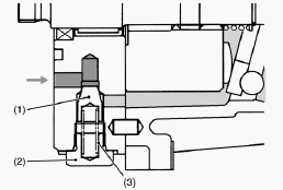
1 - Charge Relief Cone, 2 - Plug, 3 - Spring
While pumped and filtered oil flows into the main oil circuit through
the check and high pressure relief valves, and excessive oil passes to
the housing through the charge relief valve. Oil temperature - 50C
(122F). Valve operating pressure - 294 to 490 kPa (42.7 to 71.1 psi).
Check and High Pressure Relief Valve
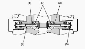
1 - Relief Valve, 2 - Check Valve, 3 - Relief Valve, 4 - Relief Spring,
5 - Check Spring
The check and high pressure relief valves monitor the oil pressure in
each line of the main oil circuit. In neutral, both check valves are
open and charging oil enters into the main oil circuit through the
valves. At normal operation, the check valve in the high pressure side
is closed and it pushes and opens the another one. When excessively high
pressure is built up in one line, the high pressure relief valve located
in this line is open and the oil flows into another line. Oil
temperature - 50C (122F). Relief valve operating pressure - 13.7 MPa
(1991 psi).
Kubota BX2200, BX2230, BX2350, BX22 Tractor -
Power Take-Off System
PTO Clutch and Valve
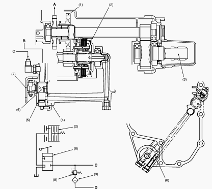
1-PTO Select Gear, 2-PTO Clutch Pack, 3-Rear PTO Shaft, 4-Transmission
Case, 5-Front Cover, 6-PTO Clutch Valve, 7-PTO Clutch Arm, 8-PTO Relief
Valve, 9-Oil Filter Cartridge, A-To Mid-PTO Shaft, B-Connected to PTO
Relief Valve, C-From Power Steering Controller, D-To Hydrostatic
Transmission
Kubota BX2200, BX2230, BX2350 tractors equipped with hydraulic
independent PTO clutch (wet multi-plates type). Therefore, the engine
power could engage or disengage to the PTO shafts without stopping the
tractor movement. The PTO clutch pack (2) has four clutch discs, four
drive plates, pressure plate, clutch piston and so on. The clutch piston
is actuated by hydraulic oil flow from the power steering controller.
The PTO clutch valve (6) controls the hydraulic oil flow from power
steering controller to the PTO clutch pack (2) by operating the PTO
clutch lever through linkage.
Power Take-Off Relief Valve
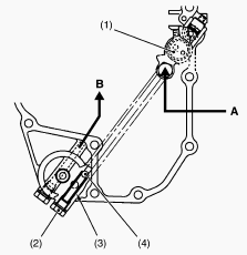
1 - PTO Clutch Valve, 2 - Plug, 3 - Spring, 4 - Steel Ball, A - From
Power Steering Controller, B - To Hydrostatic Transmission
Power Take-Off Clutch Engaged
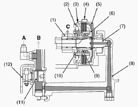
1 - 12T Gear Clutch, 2 - Brake Pressure Plate, 3 - Brake Disc, 4 -
Clutch Disc and Pressure Plate, 5 - Clutch Case, 6 - Clutch Piston, 7 -
Clutch Shaft, 8 - Transmission Case, 9 - Spring, 10 - Clutch Spline
Boss, 11 - PTO Clutch Valve, 12 - PTO Clutch Arm, A - From Power
Steering Controller, B - To Hydrostatic Transmission, C - To Mid and
Rear PTO Shaft
Power Take-Off Clutch Disengaged
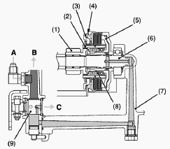
1 - 12T Gear Clutch, 2 - Clutch Spline Boss, 3 - Brake Pressure Plate, 4
- Brake Disc, 5 - Clutch Piston, 6 - Clutch Shaft, 7 - Transmission
Case, 8 - Spring, 9 - PTO Clutch Valve, A - From Power Steering
Controller, B - To Hydrostatic Transmission, C - To Transmission Case
Kubota BX2200, BX2230, BX2350, BX22
Transmission Troubleshooting
Noise from Transmission - Transmission oil
insufficient. Gear worn or broken. Bearings worn.
Gear Slip Out of Mesh - Shift fork spring tension
insufficient. Shift fork or shifter worn. Shift fork bent.
Excessive or Unusual Noise at All Time - Improper
backlash between spiral bevel pinion and bevel gear. Improper backlash
between differential pinion and differential side gear. Bearing worn.
Insufficient or improper type of transmission fluid used.
Noise while Turning - Differential pinions or
differential side gears worn or damaged. Differential lock binding (does
not disengaged). Bearing worn.
Differential Lock Can Not Be Set - Differential lock
shift fork damaged. Differential lock shifter mounting pin damaged.
Differential lock pin damaged.
Differential Lock Pedal Does Not Return - Differential
lock pedal return spring weaken or damaged. Differential lock fork shaft
rusted.
Uneven Braking Force - Brake rod unevenly adjusted.
Brake disc worn. Actuator warped.
Brake Drags - Brake pedal free travel too small. Ball
holes of actuator for uneven wear. Brake pedal return spring weaken or
broken. Brake cam rusted.
Poor Braking Force - Brake pedal free travel excessive.
Brake disc worn. Actuator warped. Brake cam or lever damaged.
Transmission fluid improper.
PTO Clutch Slip - Operating pressure is low. PTO clutch
valve malfunctioning. Clutch disc or drive plate excessively worn.
Deformation of clutch piston.
PTO Shaft Does Not Rotate - PTO clutch malfunctioning.
PTO Clutch Operating Pressure is Low - Transmission oil
improper or insufficient. Relief valve malfunctioning.
PTO Clutch Drags - Brake plate excessive worn. Clutch
spring weaken or broken. Deformation of pressure plate or steel plate.
Kubota BX2200, BX2230, BX2350, BX22 -
Transmission Disassembling and Assembling
Levers and Mower Lift Arm
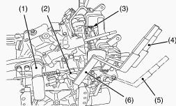
1-Mower Lift Arm, 2-Feedback Rod, 3-Rue Ring, 4-Hydraulic Control Lever,
5-Front Wheel Drive Lever, 6-Range Gear Shift Lever
Tap out the spring pin from the range gear shift lever (6) and front
wheel drive lever (5), then remove the both levers. Remove the mower
lift arm (1) with feedback rod (2). Remove the rue ring (3) and
hydraulic control lever mounting bolt and nut, then remove the hydraulic
control lever (4).
Neutral Plate and Neutral Switch Stay
Remove the trunnion arm mounting bolt and nut. Remove the neutral plate
mounting screws, then remove the neutral plate. Remove the neutral
switch stay.
Hydrostatic Transmission Assembly
Remove the hydrostatic transmission assembly from transmission case.
Apply oil to the O-rings and take care not to damage them. Apply liquid
lock to the thread of hydrostatic transmission mounting screws.
Center Section and Charge Relief Valve
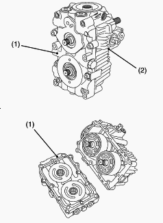
1-Center Section, 2-HST Housing
Remove the center section mounting hex. socket head screws. Tap the
center section (1) with soft hammer and separate the center section (1)
from the HST housing (2). Cover the splines of each shaft with thin tape
to protect the sealing lip of the oil seals. Place a new gasket on the
HST housing. Take care not to damage the surface of cylinder blocks,
pistons and center section. Charge Relief Valve - Remove the plug and
draw out the spring and charge relief cone. Take care not to damage the
O-ring on the plug.
Check and High Pressure Relief Valve
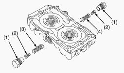
1-Plug, 2-Spring, 3-Check and High Pressure Relief Valve Assembly
(Forward), 4-Check and High Pressure Relief Valve Assembly (Reverse)
Remove the plug (1) and draw out the spring (2) and check and high
pressure relief valve assembly (3), (4). Take care not to damage the
O-ring on the plug.
Cylinder Block Assembly and Thrust Ball
Bearing
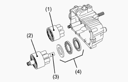
1-Cylinder Block Assembly (Pump Side), 2-Cylinder Block Assembly (Motor
Side), 3-Motor Shaft, 4-Thrust Ball Bearing
Remove the cylinder block assembly (pump side) (1). Remove the cylinder
block assembly (motor side) (2) with the motor shaft (3). Remove the
thrust ball bearing (4). Apply clean transmission oil to thrust ball
bearing, cylinder block and piston.
Swashplate and Pump Shaft
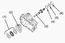
1-Thrust Roller Bearing, 2-Swashplate, 3-Pump Shaft, 4-Spacer, 5-Oil
Seal, 6-Internal Snap Ring
Remove the swashplate (2) and thrust roller bearing (1) from the HST
housing. Remove the internal snap ring (6) and tap out the pump shaft
(3), spacer (4) and oil seal (5). Apply clean transmission oil to the
thrust roller bearing.
Cradle Bearing, Slot Guide and Trunnion Arm
Remove the slot guide and trunnion arm. Remove the cradle bearing from
the HST housing. Apply clean transmission oil to the cradle bearing and
trunnion arm. Fasten down the cradle bearing to the HST housing.
Kubota BX2200, BX2230, BX2350, BX22 -
Transmission Case Disassembly and Assembly
Levers and Mower Lift Arm
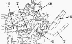
1-Mower Lift Arm, 2-Feedback Rod, 3-Rue Ring, 4-Hydraulic Control Lever,
5-Front Wheel Drive Lever, 6-Range Gear Shift Lever
Tap out the spring pin from the range gear shift lever (6) and front
wheel drive lever (5), then remove the both levers. Remove the mower
lift arm (1) with feedback rod (2). Remove the rue ring (3) and
hydraulic control lever mounting bolt and nut, then remove the hydraulic
control lever (4).
Neutral Plate and Neutral Switch Stay
Remove the trunnion arm mounting bolt and nut. Remove the neutral plate
mounting screws, then remove the neutral plate. Remove the neutral
switch stay.
PTO Select Lever and Control Valve
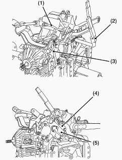
1-Delivery Pipe, 2-PTO Select Lever, 3-PTO Clutch Rod, 4-PTO Safety
Switch Stay, 5-Control Valve
Remove the delivery pipe (1) and PTO clutch rod (3). Tap out the spring
pin and remove the PTO select lever (2). Remove the control valve (5)
with PTO safety switch stay (4). Apply oil to the O-rings and take care
not to damage them.
Hydraulic Pump and Suction Pipe
Remove the hydraulic pump and suction pipe from the transmission case.
Do not twist the suction hose. Take care not to damage the O-rings.
Seat Rail Front Stay and Hydrostatic
Transmission Assembly
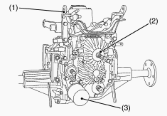
1-Seat Rail Front Stay, 2-Hydrostatic Transmission Assembly, 3-Oil
Filter Cartridge
Remove the seat rail front stay (1). Remove the hydrostatic transmission
assembly (2) and oil filter cartridge (3). Apply oil to the O-rings and
take care not to damage them. Apply liquid lock (Three Bond 1324 or
equivalent) to the thread of hydrostatic transmission mounting screws.
Kubota BX2200, BX2230, BX2350, BX22 -
Hydraulic Cylinder
Remove the hydraulic cylinder mounting screws and dismount the hydraulic
cylinder. Apply liquid gasket to joint face of the transmission case to
hydraulic cylinder.
Front Cover
Remove the front cover mounting screws and separate the front cover.
Apply liquid gasket to joint face of the transmission case to front
cover. The spring pin on the front wheel drive idle shaft and gear pump
idle shaft should face upper side. Apply grease to the collar on the
front wheel drive shaft. Take care not to damage the O-ring.
PTO Clutch Valve
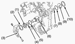
1-PTO Clutch Sleeve, 2-Internal Snap Ring, 3-PTO Clutch Arm, 4-O-ring,
5-O-ring, 6-PTO Clutch Valve, 7-O-ring, 8-O-ring, 9-PTO Clutch Collar,
10-Internal Snap Ring
Remove the PTO clutch arm (3). Remove the internal snap ring (10), then
draw out the PTO clutch collar (9) and PTO clutch valve (6). Remove the
internal snap ring (2) and draw out the PTO clutch sleeve (1). Take care
not to damage the O-rings.
Front Wheel Drive Shaft and Shift Fork
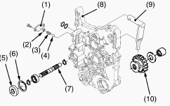
1-Plate, 2-O-ring, 3-Spring, 4-Steel Ball, 5-Oil Seal, 6-Internal Snap
Ring, 7-Front Wheel Drive Shaft, 8-Front Cover, 9-Front Wheel Drive
Shift Fork, 10-19T Shifter Gear
Remove the plate (1), then draw out the spring (3) and steel ball (4).
Remove the oil seal (5) and internal snap ring (6). Tap out the front
wheel drive shaft (7) to the front. Remove the 19T shifter gear (10) and
front wheel drive shift fork (9). Take care not to damage the O-ring.
Replace the oil seal (5) with new one.
13T Gear, 19T Gear Shaft, Hydraulic Pump Idle
Shaft, Mid-PTO Shaft and Mid-PTO Idle Shaft
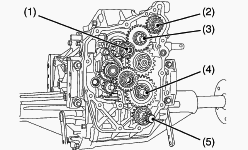
1 - 13T Gear Assembly, 2 - 19T Gear Shaft Assembly, 3 - Hydraulic Pump
Idle Shaft Assembly, 4 - Mid-PTO Idle Shaft Assembly, 5 - Mid-PTO Shaft
Assembly
Remove the 13T gear assembly (1), 19T gear shaft assembly (2) and
hydraulic pump idle shaft assembly (3). Remove the mid-PTO shaft
assembly (5) and mid-PTO idle shaft assembly (4).
Spiral Bevel Gear Shaft, 17T-25T Gear Shaft
and Front Wheel Drive Idle Shaft
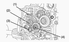
1 - Range Gear Shift Fork, 2 - Spiral Bevel Gear Shaft Assembly, 3 -
Front Wheel Drive Idle Shaft Assembly, 4 - 17T-25T Gear Shaft Assembly
Remove the front wheel drive idle shaft assembly (3) and 17T-25T gear
shaft assembly (4). Remove the spiral bevel gear shaft assembly (2)
together with range gear shift fork (1). Install all of the above
mentioned parts, simultaneously.
Rear Cover, Rear PTO Shaft and Rear PTO Drive
Shaft
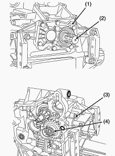
1-Rear Cover, 2-Rear PTO Shaft Assembly, 3-PTO Select Bolt, 4-Rear PTO
Drive Shaft Assembly
Remove the rear cover (1) and rear PTO shaft assembly (2). Remove the
PTO select bolt (3) and draw out the spring and steel ball. Remove the
rear PTO drive shaft assembly (4). Apply liquid gasket to joint face of
the transmission case to rear cover. Apply grease to the lip of oil
seal.
Final Gear Shaft and Differential Gear
Assembly
Draw out the final gear shaft assembly, differential gear assembly and
differential lock shift fork. Take care not to damage the O-ring.
Kubota BX2200, BX2230, BX2350, BX22 -
Disassembling Differential Gear Assembly
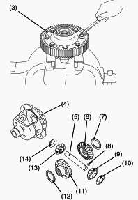
3 - 66T Final Gear, 4 - Differential Case, 5 - Differential Pinion
Shaft, 6 - Differential Side Gear, 7 - Differential Side Gear Washer, 8
- Key, 9 - Differential Pinion, 10 - Differential Pinion Washer, 11 -
Differential Side Gear, 12 - Differential Side Gear Washer, 13 -
Differential Pinion, 14 - Differential Pinion Washer
Remove the bearing (1), differential lock shifter (2) and 66T final gear
(3). Put parting marks on the differential pinions (9), (13) and the
differential side gears (6), (11). Tap out the differential pinion shaft
(5). Remove the differential pinions (9), (13), differential pinion
washers (10), (14), differential side gears (6), (11) and differential
side gear washers (7), (12). Install the differential pinion and
differential side gear, aligning the parting marks. Lock the
differential pinion shaft (5) by setting the key (8).
Brake Disc and Friction Plate
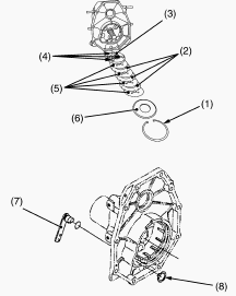
1-Internal Snap Ring, 2-Friction Plate, 3-Actuator, 4-Steel Ball,
5-Brake Disc, 6-Bearing Holder, 7-Cam Lever, 8-External Snap Ring
Remove the internal snap ring (1). Remove the bearing holder (6), brake
discs (5), friction plates (2), actuator (3) and steel balls (4). Remove
the external snap ring (8), then remove the cam lever. Apply grease to
the steel balls. Install the brake discs with their holes deviation at
less than 1/3 of the total hole area. When installing the bearing
holder, do not forget to install the straight pin. Install the internal
snap ring (1) as shown in the figure. (Open end of the snap ring should
place bottom side). Take care not to damage the O-ring.
Rear Axle
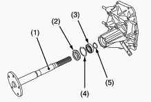
1-Rear Axle, 2-Oil Seal, 3-Bearing, 4-Internal Snap Ring, 5-External
Snap Ring
Remove the oil seal (2), then remove the internal snap ring (4). Tap out
the rear axle (1) from transmission case or rear axle cover. Do not
apply oil to the outer circumference of the oil seal.
Kubota BX2200, BX2230, BX2350, BX22 Tractor -
Transmission Servicing
Clearance between Differential Case and
Differential Side Gear
Measure the differential side gear boss O.D. with an outside micrometer.
Measure the differential case I.D. with a cylinder gauge and calculate
the clearance. If the clearance exceeds the allowable limit, replace
faulty parts. Clearance between differential case and differential side
gear - 0.050 to 0.151 mm / 0.0020 to 0.0059 in. Allowable limit - 0.30
mm / 0.0118 in. Differential case I.D. - 38.000 to 38.062 mm / 1.4961 to
1.4985 in. Differential side gear O.D. - 37.911 to 37.950 mm / 1.4926 to
1.4941 in.
Clearance between Differential Pinion Shaft
and Differential Pinion
Measure the differential pinion shaft O.D. with an outside micrometer.
Measure the differential pinion I.D. with a cylinder gauge, and
calculate the clearance. If the clearance exceeds the allowable limit,
replace faulty parts. Clearance between differential pinion shaft and
differential pinion - 0.080 to 0.122 mm / 0.0031 to 0.0048 in. Allowable
limit - 0.30 mm / 0.0118 in. Differential pinion I.D. - 20.060 to 20.081
mm / 0.7898 to 0.7906 in. Differential pinion shaft O.D. - 19.959 to
19.980 mm / 0.7858 to 0.7866 in.
Backlash between Differential Pinion and
Differential Side Gear
Secure the differential case with a vise. Set the dial indicator (lever
type) with its finger on the tooth of the differential side gear. Press
differential pinion and side gear against the differential case. Hold
the differential pinion and move the differential side gear to measure
the backlash. If the backlash exceeds the allowable limit, adjust with
differential side gear shims. Backlash between differential pinion and
differential side gear - 0.15 to 0.30 mm / 0.0059 to 0.0118 in.
Allowable limit - 0.40 mm / 0.0157 in.
Side Clearance of Spiral Bevel Pinion Shaft
Temporary assemble the spiral bevel pinion shaft and front cover to the
transmission case. Set the dial indicator (lever type) with its finger
on the end of spiral bevel pinion shaft. Move the spiral bevel pinion
shaft back and forth to each end and measure the side clearance. If the
side clearance exceeds the factory specifications, adjust with the shim
at front end of spiral bevel pinon shaft. Side clearance of spiral bevel
pinion shaft - 0.1 to 0.3 mm / 0.0039 to 0.0118 in.
Backlash between Spiral Bevel Pinion Shaft and
Spiral Bevel Gear
Temporary assemble the spiral bevel pinion shaft, and properly adjust
the side clearance. Place fuses between spiral bevel pinion shaft and
spiral bevel gear. Assemble the axle cover assembly, and turn the rear
axle. Remove the axle cover assembly, and take out the fuses. Measure
the thickness of fuses with an outside micrometer. If the measurement is
not within the factory specifications, adjust with shims. Backlash
between spiral bevel pinion shaft and spiral bevel gear - 0.1 to 0.3 mm
/ 0.0039 to 0.0118 in.
Flatness of Actuator and Bearing Holder
Place a straightedge of 150 mm (5.91 in.) or more in length on the
contacting surface of the actuator and the bearing holder. Inspect the
friction surface of the actuator and the bearing holder with the
straightedge, and determine if a 0.30 mm (0.0118 in.) feeler gauge will
fit on the part of wear. If it will fit, resurface. Flatness of actuator
and bearing holder - Allowable limit 0.30 mm / 0.0118 in.
Height of Cam Plate and Ball
Measure the height of the cam plate with the ball installed. If the
measurement is less than the allowable limit, replace the cam plate and
balls. Inspect the ball holes of cam plate for uneven wear. If the
uneven wear is found, replace it. Height of cam plate and ball - 22.89
to 22.99 mm / 0.9012 to 0.9051 in. Allowable limit - 22.40 mm / 0.8819
in.
Brake Disc and Friction Plate Wear
Measure the brake disc thickness and the friction plate thickness with
an outside micrometer. If the thickness is less than the allowable
limit, replace it. Brake disc thickness - 3.3 to 3.5 mm / 0.130 to 0.138
in. Allowable limit - 3.0 mm / 0.118 in. Friction plate thickness - 1.92
to 2.08 mm / 0.0756 to 0.0819 in. Allowable limit - 1.52 mm / 0.0598 in.
________________________________________________________________________________
________________________________________________________________________________________
| KUBOTA TRACTORS SPECIFICATIONS |
________________________________________________________________________________________
________________________________________________________________________________________
________________________________________________________________________________________
________________________________________________________________________________________
________________________________________________________________________________________
________________________________________________________________________________________
________________________________________________________________________________________
________________________________________________________________________________________
________________________________________________________________________________________
________________________________________________________________________________________
________________________________________________________________________________________
________________________________________________________________________________________
________________________________________________________________________________________
| KUBOTA ENGINES DATA AND SERVICE SPECS |
________________________________________________________________________________________
________________________________________________________________________________________
________________________________________________________________________________________
________________________________________________________________________________________
________________________________________________________________________________________
| KUBOTA FRONT END LOADERS |
________________________________________________________________________________________
________________________________________________________________________________________
________________________________________________________________________________________
________________________________________________________________________________________
________________________________________________________________________________________
________________________________________________________________________________________
________________________________________________________________________________________
________________________________________________________________________________________
________________________________________________________________________________________
________________________________________________________________________________________
________________________________________________________________________________________
________________________________________________________________________________________
| KUBOTA TRACTORS TROUBLESHOOTING | ||||
| L235 | L2501 | L2550 | L275 | L3110 |
| L3301 | L35 | L3710 | L3901 | L4310 |
| L5030 | M4700 | M5700 | M6040 | M6800 |
| M8200 | M8540 | M9000 | MX5100 | MX5200 |
 SPECIFICATIONS
 LOADERS
 ENGINES
 MAINTENANCE
 PROBLEMS
 B1241
B1241 B1600
B1600 B1700
B1700 B1750
B1750 B21 Backhoe
 B2150
B2150 B2301
B2301 B2320
B2320 B2530
B2530 B26 Backhoe
 B2601
B2601 B2650HSD
 B3030
B3030 B3350
B3350 B6000
B6000 B6100
B6100 B6200
B6200 B7000
B7000 B7001
B7001 B7100HST
 B7200
B7200 B7500
B7500 B7510
B7510 B7800
B7800 B8200HST
 BX1880
 BX2200
 BX2230
 BX2350
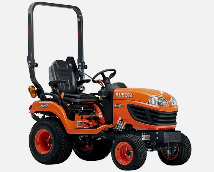 BX2370
 BX23S
BX23S BX25 TLB
 BX2660
 BX2680
 F3680
F3680 L175
L175 L185
L185 L210
L210 L225
L225 L235
L235 L245
L245 L260
L260 L275
L275 L285
L285 L305
L305 GR2120
 L1501
L1501 L2350
L2350 L2550
L2550 L2800
L2800 L3010
L3010 L3200HST
 L3301
L3301 L3560
L3560 L3800
L3800 L4701
L4701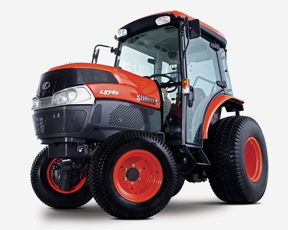 L5740
L5740 M5-091
 M5-111
 M6060
M6060 M7040
M7040 M9540
M9540 M9960
M9960 MX5100
 D662
D662 D722
D722 D750
D750 D782
D782 D850
D850 D902
D902 D905
D905 D950
D950 D1005
D1005 D1100
D1100 D1105
D1105 D1503
D1503 D1703
D1703 D1803
D1803 V1200
V1200 V1205
V1205 V1305
V1305 V1505
V1505 V2203
V2203 V2403
V2403 Z482
Z482 Z602
Z602 Z750
Z750 Z1100
Z1100 Z1300
Z1300 B1630
B1630 BF400
BF400 BF400G
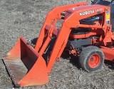 LA181
LA181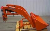 LA203
LA203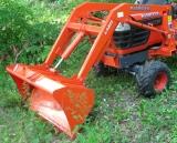 LA211
LA211 LA243
LA243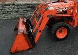 LA271
LA271 LA272
LA272 LA301
LA301 LA302
LA302 LA304
LA304 LA340
LA340 LA344
LA344 LA351
LA351 LA352
LA352 LA364
LA364 LA401
LA401 LA402
LA402 LA434
LA434 LA463
LA463 LA481
LA481 LA482
LA482 LA504
LA504 LA513
LA513 LA514
LA514 LA524
LA524 LA525
LA525 LA534
LA534 LA555
LA555 LA680
LA680 LA681
LA681 LA682
LA682 LA703
LA703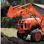 LA714
LA714 LA723
LA723 LA724
LA724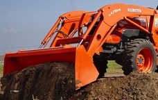 LA764
LA764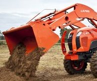 LA765
LA765 LA805
LA805 LA844
LA844 LA852
LA852 LA853
LA853 LA854
LA854 LA1002
 LA1055
 LA1065
 LA1153
 LA1154
 LA1251
 LA1301S
 LA1353
 LA1403
 LA1601S
 LA1854
 LA1944
 LA1953
 LA2253
 LM2605