________________________________________________________________________________
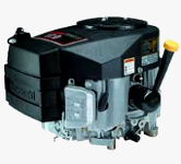
Kawasaki FB460V Carburetor
Kawasaki FB460V Carburetor Operation
In the choke or start position, the choke valve is closed, and the only
air entering the engine enters through opening around the valve. As the
starting device is operated to start the engine, the air pressure in the
carburetor is reduced as air drawn into the engine.
Since the air passage is blocked by the choke valve, fuel is drawn from
the main nozzle and from both idle fuel discharge ports and mixes with
the air that passes through the throttle valve. This makes a very rich
fuel mixture required to start a cold engine.
At idle a relatively small amount of fuel is required to operate the
engine. The throttle is almost closed, shutting off the fuel supply from
all except the one idle fuel discharge orifice, so that the suction
created by the engine draws fuel only from that orifice. During
intermediate operation, second and third orifices are uncovered as the
throttle valve opens, and more fuel is allowed to mix with the air
flowing into the engine.
During high speed operation, the throttle valve is fully opened. Air
flows through the carburetor at high speed. The venturi, which decreases
the air passage through carburetor, further accelerates the air flow.
This high speed movement of the air decreases the air pressure, and fuel
is drawn into the air stream through the main nozzle that opens into
venturi, mining with the air in the air passage.
As the engine load increases, air is automatically bled into the main
nozzle through the air jet located in the air horn. This allows fuel to
be metered freely from the main nozzle and to be facilitated
atomization.
General Specifications
Main Jet (FB460V-AS) - #112.5
Main Jet (FB460V-BS) - #115
Pilot Jet - #47.5 / #47.5
Pilot Screw (Turn out) - 1-1/8
Float Valve - 1.5 mm (0.059 in.)
Low Idle Speed - 1350 to 1450 rpm
Fast Idle Speed - 3275 to 3425 rpm
Float Level - Float parallel to carburetor body-to-bowl mating surface.
Kawasaki FB460V Carburetor Adjustment
Adjust idle mixture
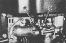
Air cleaner must be assembled to engine. Turn idle mixture screw (B) in
until it just seats, then back it out 1-1/8 turns. Do not turn the screw
in too far. The pointed end of valve seat is susceptible to damage.
Start and allow engine to warm. Move throttle lever on equipment to
"IDLE POSITION".
Use a tachometer and adjust throttle stop screw (A) to obtain 1350 to
1450 rpm by turning it in or out while holding the end of the screw
against carb body. Adjust idle mixture screw (B) by turning clockwise
(lean) or counterclockwise (rich) to obtain the peak of idling. Turn
idle mixture screw (B) back out 1/4 turn more. Use a tachometer and
readjust throttle stop screw (A) to obtain and satisfy specified 1350 to
1450 rpm idling. Stop the engine.
Removal and Disassembly
Before removing for repair, check for signs of air leakage, or mounting
gaskets that are loose, deteriorated, or otherwise damaged. Do not bent
the links or stretch. Pull carb free, and gently twist carb. to free
link rod. Remove governor link rod and link spring. Disassemble carb.
Kawasaki FB460V Carburetor
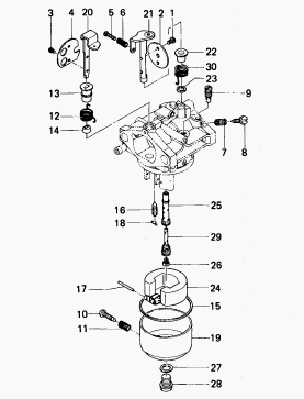
Disassembly: 1 - Screw, 2 - Throttle valve, 3 - Screw, 4
- Choke valve, 5 - Screw, 6 - Spring, 7 - Spring, 8 - Pilot screw, 9 -
Pilot jet, 10 - Drain screw, 11 - Spring, 12 - Spring, 13 - Ring, 14 -
Ring, 15 - Gasket, 16 - Needle valve, 17 - Float pin, 18 - Clip, 19 -
Float chamber, 20 - Choke shaft, 21 - Throttle shaft, 22 - Ring, 23 -
Seal, 24 - Float, 25 - Main nozzle, 26 - Main jet, 27 - Washer, 28 -
Bolt, 29 - Bleed pipe, 30 - Spring
Cleaning and Inspect
Place carb body and parts in PT503 cleaner or its equivalent. Do not put
gaskets and plastic parts in cleaner. Parts should remain in cleaner for
1 or 2 hours. Remove and rinse with solvent. Rinse carb body in hot
water to neutralize corrosive action of cleaner on aluminum. Dry parts
with compressed air. Be sure all holes are open. Do not use rags or
paper to dry parts. Lint may plug hole or passages.
Inspect carb body for damage. Flange sealing surfaces should be smooth
and free of burrs and nicks. Replace gasket if necessary. Inspect pilot
screw and drain screw for wear at the seating surface. Inspect for weak
springs. Inspect main jet, bleed pipe, main nozzle and pilot screw for
damage. Inspect inlet needle valve for wear or damage at the seating
surface. Inspect clip for damage. Inspect the other parts of carburetor
for wear, damage.
Assembly and Installation
Reassembly is the reverse of removal. Note the following points: Install
main nozzle, bleed pipe, and main jet by turning clockwise into
carburetor body. Do not over tighten screws. Install pilot screw
(mixture screw) and spring finger tight. Install pilot jet screw by
turning it clockwise into carb body.
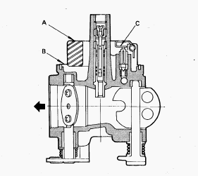
Do not over tighten. Install float and float pin. Do not push on float
or, inlet needle valve when adjusting float level. When carburetor is
upside down, float surface (A) must be parallel to carburetor body (B).
To adjust float surface angle, bend tang (C) with needle-nose pliers.
Install throttle linkages and choke linkage on carburetor. Install
breather connector on intake pipe. Assembly gaskets, heat shield plate,
carburetor, gasket and intake pipe. Install carb assembly on inlet pipe
with through bolts.
________________________________________________________________________________
________________________________________________________________________________________
| KOHLER ENGINES SPECS AND SERVICE DATA |
 CH12.5
 CH14S
CH14S CH15S
CH15S CH16
CH16 CH18S
CH18S________________________________________________________________________________________
 CH23S
CH23S CH25S
CH25S CH640S
 CH730S
 CH750S
________________________________________________________________________________________
________________________________________________________________________________________
 CV15S
CV15S CV16S
CV16S CV18S
CV18S CV20S
CV20S CV22S
CV22S________________________________________________________________________________________
 CV23S
CV23S CV25S
CV25S CV490S
 CV491S
 CV730S
________________________________________________________________________________________
 CV740S
 K161
K161 K181
K181 K241
K241 K301
K301________________________________________________________________________________________
 K321
K321 K341
K341 K361
K361 M18
M18 M20
M20________________________________________________________________________________________
 SV470S
 SV530S
 SV540S
 SV590S
 SV600S
________________________________________________________________________________________
 SV710
SV710 SV715
SV715 SV725S
 SV730S
 SV735
SV735________________________________________________________________________________________
| KAWASAKI ENGINES SPECS AND SERVICE DATA |
 FA210
FA210 FA210D
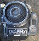 FB460V
 FC150V
 FC290V
________________________________________________________________________________________
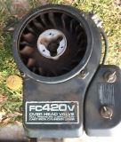 FC420V
 FC540V
 FD501V
 FD590V
 FD620D
________________________________________________________________________________________
 FD731V
 FD750D
 FH430V
 FH500V
 FH531V
________________________________________________________________________________________
 FH580V
 FH601V
 FH680V
 FS541V
 FS600V
________________________________________________________________________________________
 FS651V
 FX651V
 FX691V
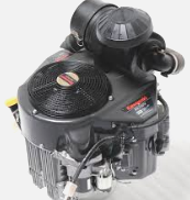 FX730V
________________________________________________________________________________________
 FH541V
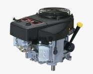 FH641V
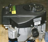 FH661V
 FH721V
 FS730V
________________________________________________________________________________________
| BRIGGS AND STRATTON ENGINES SPECIFICATIONS |
 252707
 253707
 282707
 286707
 303777
________________________________________________________________________________________
 28N707
 28M707
 28Q777
 28R707
 28S777
________________________________________________________________________________________
 311707
 31A607
 31C707
 31N707
 31Q777
________________________________________________________________________________________
 31R977
 31R777
 31P777
 31P977
 350777
________________________________________________________________________________________
 402707
 422707
 42A707
 331777
 331877
________________________________________________________________________________________
| HONDA ENGINES SPECS AND SERVICE DATA |
 G50
G50 G100
G100 GC135
GC135 GC160
GC160 GC190
GC190________________________________________________________________________________________
 GS190
GS190 GX100
GX100 GX120
GX120 GX160
GX160 GX200
GX200________________________________________________________________________________________
 GXV120
 GXV160
 GXV270
 GXV340
 GXV390
________________________________________________________________________________________
 GXV610
 GCV520
 GCV530
 GXV620
 GXV630
________________________________________________________________________________________
 GCV145
 GCV160
 GCV170
 GCV190
 GCV200
________________________________________________________________________________________
 GSV190
 GX110
GX110 GX140
GX140 GV100
GV100 GXV140
________________________________________________________________________________________