________________________________________________________________________________
John Deere 5620, 5720, 5820 Hydraulics and Hitch
JD 5620, 5720, 5820
Hydraulic System
Selective Control Valves
The 5620, 5720, 5820 John Deere tractor may be equipped one of three
different types of selective control valve: 105 Series, 205 Series or
305 Series. 105 Series
selective control valves provide the functions "Raise", "Neutral" and
"Lower". 205 and 305 Series selective control valves provide an
additional "Float" position.
Series 305 selective control valves also offer the following choices:
- The control lever remains in the "Raise" or "Lower" position until it
is moved manually.
- The control lever moves to "neutral" as soon as it is released.
- The control lever remains in the "Raise" or "Lower" position until the
pressure in the oil circuit has reached a predetermined value (e.g. when
the remote control
cylinder has reached its end position).
Levers for Selective Control Valves
A - Retract, B - Extend, C - Neutral position, D - Float position
- The control lever has four settings. The remote cylinder retracts when
the lever is moved to the "Retract" position.
- The remote cylinder extends when the lever is moved to the "Extend"
position. The remote cylinder is held in place when the lever is in
"Neutral".
- When the lever is in the "Float" position (i.e. piston moves freely
inside remote cylinder), the mounted implement follows the ground
contours.
- If additional external valves are used, move the control lever to
neutral when shutting off each hydraulic function.
- Locks (A) allow the control levers to be secured in neutral.
- Apply locks (A) when driving on roads and whenever the control levers
are in neutral because they are not required.
Multi-Function Lever
A - Multi-function lever, B - Buttons for additional functions, C -
Transport lock slide control, D - Upshift/downshift buttons
- Multi-function lever (A) permits two SCVs to be operated at the same
time. Buttons (B) allow additional functions to be performed.
- The slide control (C) can be used to lock the lever.
- The multi-function lever must be locked when the John Deere 5620,
5720, 5820 tractor is driven on proper roads.
- If upshift/downshift buttons (D) are equipped, they allow the gears at
the transmission to be shifted.
Rate of Cylinder Operation - The flow control valve can be used to
adjust rate at which the rockshaft rises and drops (with 305 Series
selective control valves only).
Full extension and retraction of a remote cylinder should require at
least 1.5 seconds. Faster speeds may cause damage.
Remote Hydraulic Cylinder - The total retract stroke may be varied from
0 to 203 mm (0-8 in.) by means of the adjustable stop. Turn adjustable
stop so that stop
rod arm does not come into contact with stop lever. After the adjustable
stop comes into contact with the stop rod arm, a further 38 mm (1.5 in.)
of slow travel is
gained if remote cylinder control lever is held in "retract" position.
Changing Hydraulic Oil
- Start engine and operate several hydraulic functions to heat up oil.
- Park JD 5620, 5720, 5820 tractor so that it is level. Lower draft
links and front-mounted implements.
- Shut off engine and remove key. Apply the parking brake (Transmission
in neutral).
- Remove drain screws (A). Replace hydraulic oil filter elements (B).
- At the left side of the tractor underneath the rear axle, take out
plug (C), remove the intake screen and wash it in fuel.
- Before refilling with fresh oil, reinstall intake screen, replace
seals and tighten drain screws to 50 N·m (35 lb-ft).
- Add hydraulic oil to the transmission case.
Front Three-Point Hitch
This three-point hitch can be operated with SCV I.
Multi-valve
The additional multi-valve allows the following settings:
- Oil flow blocked.
- Raising with oil pressure, lowering with deadweight of implement.
- Raising and lowering with oil pressure.
If SCV I is equipped with additional couplers towards the rear (for
operation of rear implements), the multi-valve must be blocked before
rear implements are
operated using SCV I. When a chain is used to limit the cutting height
on a mowing unit, avoid damage by selecting setting. Additionally, set
SCV I to float position to
lower the mowing unit.
Couplers
Oil pressure is available at coupler when the hitch is raised. Couplers
are provided with oil via SCV II or III.
The couplers allow the hydraulic hose to be connected and disconnected
only if no pressure is present. For coupler this means that the front
hitch must be lowered.
To connect the hose union, press it firmly into the coupler. To
disconnect the hose, give it a firm pull.
Brackets for mowing unit suspension (if equipped) - Opening allows
attachment of the chain for cutting height limit. In this case, avoid
damage by selecting setting
for the multi-valve. Additionally, set SCV I to float position to lower
the mowing unit. Bore allows attachment of the suspension spring.
Hydraulic System Troubleshooting
| Hydraulic system fails to function | Not enough oil in the system | Top up to mark on dipstick. |
| Hydraulic oil overheats | Clogged hydraulic filters | Replace hydraulic filters. |
| Dirt in hydraulic pump | Check filter for clogging. | |
| Oil cooler air passages clogged | Clean oil cooler. | |
| Dirt in hydraulic pump | Check filter for clogging. |
| Hitch fails to lift load | Excessive load on hitch | Adjust auxiliary springs on implement or reduce load. |
| Hitch drops too slowly | Rate-of-drop regulator not adjusted properly | Adjust rate of drop. |
| No hitch response to draft load | System regulator in Height or Load-and-Depth Control position | Place system regulator in Load Control position. |
| Hitch too active | System regulator in Load Control position | Place system regulator in Load-and-Depth position. |
| Direction of remote cylinder travel is reversed | Hoses connected incorrectly | Connect hoses correctly. |
| Remote cylinder will not lift load | Excessive load | Adjust auxiliary springs on implement or reduce load. |
| Hoses on quick-coupler not correctly attached | Attach hoses to quick-coupler correctly. | |
| Air in remote cylinder | Bleed cylinder. |
| Remote cylinder travels too fast or too slowly | Rate-of-lift is adjusted incorrectly | Adjust rate of lift. |
John Deere 5620, 5720, 5820 Hitch and Drawbar
Hitch Dampening
The 5620, 5720, 5820 John Deere tractor is equipped with a hitch dampening function that prevents the tractor from "pitching" when it is travelling with a raised implement. To activate the dampening function, first move hitch control lever (A) (with the engine running) to the position that corresponds to the position of the draft links.
Then pull it as far as it will go to the rear (beyond "0") to the transport position (see arrow). The rate-of-drop control must NOT be in the left-hand end position. To switch off the dampening function, push the hitch control lever forward from the transport position to a position beyond "0" (in the "drop" direction).
Adjustable Drawbar
The drawbar is used to pull drawn equipment of all types, particularly PTO-driven implements. The drawbar hitch is located so as to increase the rear axle load and at the same time slightly reduce load on the front axle. Besides having a variable swinging range, the drawbar can also be adjusted lengthwise. Maximum permissible static vertical loads and towable drawbar loads are stated in the Specifications. Towing on public roads with the swinging drawbar set to one side is not permitted!
A - Hex Plug, B - Locking pin, C - Drawbar
The drawbar can be adjusted to three different lengths: 250 mm (9.8 in.), 350 mm (13.8 in.) and 400 mm (15.7 in.). These lengths determine the distance from the end of the PTO shaft to the attachment point of the drawbar.
- Remove hex plug (A).
- Remove locking pin (B).
- Adjust drawbar (C) and reinstall locking pin.
- Tighten hex plug (A) to 310 Nm (225 lb-ft).
Height-Adjustable Trailer Hitch
- The JD 5620, 5720, 5820 tractor can be equipped with different hitch versions which are operated in different ways.
- The height of all hitches can be adjusted using lever. On hitch the hitch pin is operated using handle.
- Hitches can be opened and closed by means of lever. Hitches can also be closed by inserting the trailer towing eye.
- Use only trailer hitches with a towing eye diameter of 40 mm (137 / 64 in.).
- Trailer hitches with different dimensions may be available in certain countries.
Pick-Up Hitch
This type of hitch can be operated via the rockshaft and one selective control valve.
- Connect hydraulic hoses to the quick-couplers. Raise draft links to maximum height and use SCV to retract the hitch hook fully.
- Pull release lever and hold it until the hitch hook has moved from the stored position (lever remains in "open" position).
- Extend the hitch hook fully by actuating the selective control valve. Lower draft links/hitch hook to desired height.
- Raise draft links to engage hitch hook in trailer towing eye, then continue to raise the hitch fully.
- Retract the hitch hook fully by means of selective control valve until it is fully locked (lever returns to its starting position).
- Lower the draft links. Check that the hitch is locked correctly.
- It will not lower when the draft links are lowered and not extend when the selective control valve is operated.
- Hook of pick-up hitch can be replaced by a drawbar without the use of tools. To do so, lift out pin.
Rockshaft Control
The rockshaft is controlled by means of hitch control lever and raise/lower switch. The lift height can be limited by means of the height-limit control.
To make the rockshaft ready for operation, start the engine and either:
- Move control lever to the position that corresponds to the position of draft links.
- Move control lever to one of the end positions, or actuate raise/lower switch.
- Pull control towards "0" - raise implement.
- Push control towards "9" - lower implement.
The implement can be raised and lowered independently of control lever by means of raise/lower switch. This is of assistance when turning at the end of a field, for example. If the upper part of the raise/lower switch is pressed, the implement is raised as high as the setting at height-limit control. If the lower part of the raise/lower switch is pressed, the implement is lowered as far as the setting at control lever. To obtain working depth more quickly in compact soil at the headland (quick lower), keep raise/lower switch pressed. As long as raise/lower switch is pressed, the adjusted draft force is not active (override function). If raise/lower switch is released, the implement returns to the previous settings.
This "quick lower" function will only work if:
- The implement has been raised using switch.
- The implement is lowered continuously from raised position using switch.
- Pull control lever as far as it will go (beyond "0") - rockshaft is locked.
Headland Management System HMS II (If Equipped) - Basic Principles
HMS II makes it possible to record and save sequences of functions that occur repeatedly and to call them up as programs when needed (tape recorder principle). Two such programs can be stored at any one time. Each of them can include up to 20 functions. The programs remain in the memory until they are deleted, even if the electrical current is switched off.
Recordings may be made of the functions of the following tractor sub-assemblies: differential lock, rockshaft, rear PTO, front PTO and front-wheel drive. The distance the tractor moves between functions is also stored. The recording is therefore not dependent on the tractor's speed.
Sample programming (end/start of field)
Initial situation: JD 5620, 5720, 5820 tractor operating in field, rear implement is lowered, front-wheel drive is on, rear PTO is on.
- Press HMS II on/off switch - Acoustic signal, HMS II indicator light comes on.
- Press Record/save switch - Acoustic signal every 2 seconds, light flashes.
- Press Program switch to "1" or "2" - Indicator Light or flashes.
- Raise rear implement - The tractor must be driven at a speed of at least 0.5 km/h (0.31 mph).
- Switch off rear PTO - The tractor must be driven at a speed of at least 0.5 km/h (0.31 mph).
- Switch off front-wheel drive - This step may be performed with the tractor stationary (clutch depressed).
- Press switch Record/save - Light goes out, HMS II indicator light remains on continuously (not flashing).
Initial situation: John Deere 5620, 5720, 5820 tractor is at the headland, rear implement is raised, front-wheel drive is off, rear PTO is off.
- Press Record/save switch - Acoustic signal every 2 seconds, HMS II indicator light flashes.
- Press Program switch to "1" or "2" - Program 1 indicator Light or Program 2 indicator flashes.
- Lower rear implement - The tractor must be driven forward at a speed of at least 0.5 km/h (0.31 mph).
- Switch on rear PTO - The tractor must be driven forward at a speed of at least 0.5 km/h (0.31 mph).
- Switch on front-wheel drive - This step may be performed with the tractor stationary (clutch depressed).
- Press Record/save switch - Light goes out, light remains on continuously (not flashing).
- Press HMS II on/off switch - Acoustic signal, light goes out.
Performing the stored programs
To enable the recorded programs to be performed, the 5620, 5720, 5820 John Deere tractor must be driven at a speed of at least 0.5 km/h (0.31 mph). Before programs are performed that include front-wheel drive and/or PTO functions, front-wheel drive and/or the PTO(s) must be switched on. HMS II cannot physically "turn on" the relevant switches. Before programs are performed that include rockshaft functions, the relevant lever must be in neutral position.
1. Pressing on/off switch makes HMS II indicator light come on.
2. To select the desired program, press program switch to "1" or "2".
Program indicator light will come on. This light goes out once the program has been completed.
Headland Management System HMS II - Details
Basic controls
On/off switch:
When this switch is actuated, an acoustic signal is emitted.
- If this switch is actuated while the HMS II mode is on, it turns the HMS II mode off.
- Actuating this switch does not activate the HMS II mode unless program switch is in its neutral position.
- If this switch is actuated while a program is being recorded, the recording of the program is interrupted and the program does not get stored in the memory.
- If this switch is actuated while a program is being performed, the program stops.
Record/save switch:
When this switch is actuated, an acoustic signal is emitted.
- If this switch is actuated while the HMS II mode is off, it has no effect.
- If this switch is actuated while the HMS II mode is on, it starts to record a program.
- If this switch is actuated while a program is being recorded, the relevant program (1 or 2) is stored in the memory.
Program switch:
- If this switch is actuated while the HMS II mode is off, it has no effect.
- If this switch is actuated while the HMS II mode is on, the relevant program (1 or 2) will start.
- If this switch is actuated while a program is being recorded, the following functions are allocated to the relevant program.
Differential lock: The "on"/"off" status is recorded.
Front-wheel drive: The status "brake assist (off)", "on" and "auto" is recorded. If HMS II is to perform a program that includes a front-wheel drive function, the FWD switch must be either in the "on" position or the "Auto" position. If HMS II switches FWD off, the FWD indicator light will flash "slowly" (on briefly, off for longer) until HMS II switches FWD on again or until the FWD switch is moved to its "off" position. In the event of HMS II being switched off during the period of slow flashing, the FWD indicator light changes to "rapid" flashing (on/off for the same length of time) until the FWD switch is moved to its "off" position.
Rear PTO: The "on"/"off" status is recorded. If HMS II is to perform a program that includes a PTO function, the PTO switch must be in its "on" position. If HMS II switches the PTO off, the PTO indicator light will flash "slowly" (on briefly, off for longer) until HMS II switches PTO on again or until the PTO switch is moved to its "off" position. In the event of HMS II being switched off during the period of slow flashing, the PTO indicator light changes to "rapid" flashing (on/off for the same length of time) until the PTO switch is moved to its "off" position.
Front PTO: The "on"/"off" status is recorded. If HMS II is to perform a program that includes a PTO function, the PTO switch must be in its "on" position. If HMS II switches the PTO off, the PTO indicator light will flash "slowly" (on briefly, off for longer) until HMS II switches PTO on again or until the PTO switch is moved to its "off" position. In the event of HMS II being switched off during the period of slow flashing, the PTO indicator light changes to "rapid" flashing (on/off for the same length of time) until the PTO switch is moved to its "off" position.
Rockshaft: The "raise", "lower" and "quick lower" functions are recorded. If HMS II is to perform a program that includes a rockshaft function, the rockshaft control switch must be in its neutral position.
________________________________________________________________________________
 JD SPECS
 JD LOADERS
 JD MAINTENANCE
 JD INSTRUCTIONS
 JD PROBLEMS
________________________________________________________________________________________
 JD 2025R
 JD 3039R
 JD 4044R
 JD 4105
 JD 4720
________________________________________________________________________________________
 420 Loader
 419 Loader
 510 Loader
 512 Loader
 520 Loader
________________________________________________________________________________________
 520M Loader
 540M NSL
 540 Loader
 440R Loader
 H180 Loader
________________________________________________________________________________________
 JD 5045E
 JD 5085E
 JD 5100M
 JD 6105R
 JD 6120M
________________________________________________________________________________________
 JD 6155M
 JD 6195R
 JD 6210R
 JD 7210R
 JD 7250R
________________________________________________________________________________________
 JD 7310R
 JD 8245R
 JD 8295R
 JD 8370R
 JD 9370R
________________________________________________________________________________________
 120R Loader
 D120 Loader
 H120 Loader
 45 Loader
 200CX Loader
________________________________________________________________________________________
 D160 Loader
 D170 Loader
 H160 Loader
 H165 Loader
 H240 Loader
________________________________________________________________________________________
 210 Loader
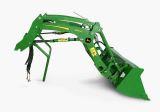 220R Loader
 300E Loader
 300X Loader
 300CX Loader
________________________________________________________________________________________
 JD 9420R
 JD 9510R
 JD GX335
 JD GX85
 JD LA105
________________________________________________________________________________________
 JD 5065M
 JD 5055D
 JD 5115R
 JD 5105M
 JD 6110R
________________________________________________________________________________________
 JD 6130D
 JD 6225
 JD 7530
 JD 4044M
 JD 7185J
________________________________________________________________________________________
 300 Loader
 300R Loader
 320R Loader
 400E Loader
 410 Loader
________________________________________________________________________________________
 430 Loader
 460 Loader
 521 Loader
 531 Loader
 541 Loader
________________________________________________________________________________________
 551 Loader
 631 Loader
 651 Loader
 661 Loader
 603R Loader
________________________________________________________________________________________
 JD D130
 JD D160
 JD 325
 JD 335
 JD 345
________________________________________________________________________________________
 JD 2520
 JD 3005
 JD 3720
 JD 1025R
 JD 3033R
________________________________________________________________________________________
 JD 5090EL
 JD 5100MH
 JD 5075GV
 JD 6090RC
 JD 6110B
________________________________________________________________________________________
 623R Loader
 643R Loader
 731 Loader
 746 Loader
 751 Loader
________________________________________________________________________________________
 533 Loader
 583 Loader
 633 Loader
 653 Loader
 683 Loader
________________________________________________________________________________________
 H260 Loader
 663R Loader
 663 Loader
 683R Loader
 753 Loader
________________________________________________________________________________________
 JD 6125J
 JD 6150RH
 JD 6210J
 JD 7195J
 JD 8310
________________________________________________________________________________________
 JD 6325
 JD 5525
 JD 5083EN
 JD 5100GN
 JD 5125R
________________________________________________________________________________________
 210C Backhoe
 300D Backhoe
 310G Backhoe
 410G Backhoe
 710G Backhoe
________________________________________________________________________________________
 80 Loader
 100 Loader
 146 Loader
 148 Loader
 158 Loader
________________________________________________________________________________________
 168 Loader
 175 Loader
 522 Loader
 542 Loader
 540R Loader
________________________________________________________________________________________
 562 Loader
 563 Loader
 673 Loader
 741 Loader
________________________________________________________________________________________
 L108 Automatic
 L120 Automatic
 LA110 Automatic
 LA120 Automatic
 LA150 Automatic
________________________________________________________________________________________
 LT155
LT155 LT160 Automatic
 LT180 Automatic
 LTR180
 X165
X165________________________________________________________________________________________
 E100
E100 E120
E120 E150
E150 LTR166
________________________________________________________________________________________
 LA135
LA135 LA165
LA165 LX277
LX277 LX288
LX288 LX255
LX255________________________________________________________________________________________
 S240
S240 GT235
GT235 G110 Automatic
 JD 3203
 JD 5520
________________________________________________________________________________________
 JD 316
 JD 420
 JD 425
 JD 445
________________________________________________________________________________________
 JD_5050D
 X300
X300 X304
X304 X310
X310 X110 Automatic
________________________________________________________________________________________
 H310 Loader
 H340 Loader
 H360 Loader
 H380 Loader
 H480 Loader
________________________________________________________________________________________
 240 Loader
 245 Loader
 260 Loader
 265 Loader
 280 Loader
________________________________________________________________________________________
 600R Loader
 620R Loader
 640R Loader
 660R Loader
 680R Loader
________________________________________________________________________________________
 JD_5039D
 X146R
X146R X360
X360 X155R
X155R X140 Automatic
________________________________________________________________________________________
 X350
X350 X380
X380 X500
X500 X590
X590 X700
X700________________________________________________________________________________________
 3036E
3036E 2038R
2038R 3038R
3038R 4049M
4049M JD 4100
________________________________________________________________________________________
 X738
X738 X740
X740 X748
X748 X749
X749 X950R
X950R________________________________________________________________________________________
 JD 4510
 5045D
5045D 5050E
5050E 5060E
5060E 5078E
5078E