________________________________________________________________________________
John Deere 5225, 5325, 5425, 5525, 5625 Hydraulic System
- JD 5225-5625 Engine
- JD 5225-5625 PTO and Hitch
- JD 5225-5625 Drivetrain
- JD 5225-5625 Hydraulic System
Connecting or
Disconnecting High-Pressure Hoses
- If possible, retract remote cylinder as much as possible to protect
rod from damage.
- Implement must be raised slightly, by pulling back on lever to reset
coupler check valves, before it can be lowered.
- If hose accidentally pulls from JD 5225, 5325, 5425, 5525, 5625
tractor during use, clean hose tip and coupler before reconnecting.
Hoses can be reinstalled with
minimal loss of oil.
- After reinstalling hose, extend and retract cylinder to properly seat
connector and reset check valve.
- With as much hydraulic pressure relieved as possible from hoses, pull
hoses from couplers.
- Rear SCV: Wipe clean, then close coupler cover. Install dust caps on
hose ends.
- Mid-Mount Valve: Make sure coupler dust plugs and hose end dust caps
are clean, then install.
Connecting Cylinder Hoses (Rear SCV)
- Identify extend and retract hoses. Extend hoses should be connected to
top couplers; retract hoses to bottom couplers.
- Remove dust caps (if equipped) from hose end.
- Open coupler covers.
- Hydraulic hoses can fail due to physical damage, kinks, age and
exposure. Check hoses regularly. Replace damaged hoses.
- Making sure hose end and coupler are clean, push hose tip firmly into
coupler. Pull on hose to make sure positive connection was made.
Connecting Cylinder Hoses (Mid-Mount Valve)
Hose connections at mid-mount valve are color-coded. Black - Bucket
Cylinder-Rod End. Yellow - Bucket Cylinder-Head End. Blue - Lift
Cylinder-Head End. Red -
Lift Cylinder-Rod End. Orange - Attachment Cylinder-Head End. Green -
Attachment Cylinder-Rod End.
- Match hoses to couplers using color-coded dust caps/plugs.
- Remove dust caps from hose ends.
- Pull dust plugs from valve couplers.
- Making sure hose end and couplers are clean, push hose tip firmly into
coupler. Pull on hose to make sure positive connection was made.
- Connect mating (color-coded) plugs and caps together.
Connecting and Operating Single-Acting Cylinder
- Single-acting cylinder should only be connected to extend coupler.
- Volume of oil required to extend cylinder will lower
transmission-hydraulic oil level.
- With cylinder fully extended, check oil level and fill to proper level
(visible at the bottom of the top sight glass).
- Pull SCV control lever back to pressurize and extend single acting
cylinder.
- Push SCV control lever full forward to "float" position to retract
cylinder.
Operating SCV Control Levers (Basic Valves)
Extend and Retract Cylinders
With hoses properly connected to couplers, pull lever back against
spring pressure to extend remote cylinder. Spring pressure returns lever
to neutral when
released. With lever in neutral, remote cylinder is hydraulically locked
in position. Push lever forward against spring pressure to retract
cylinder.
Float Position - Push lever forward, through retract, into detent to
operate "float" feature. "Float" operation allows cylinder to extend and
retract freely, such as when
an implement follows ground contour. Manually return lever to neutral
when "float" is no longer required.
Setting Detents and Operating SCV Control Levers (Deluxe Valve)
Setting Control Lever Detents - Each section of the deluxe SCV has
selectable detents, used to change control lever operations to meet
operating requirements of
different implements. Detent settings only affect extend and retract
lever positions, not "float". Read operator's manual symbol is for
reference only and is not a
selectable setting. The three settings are: Continuous Detent (Motor),
No Detent (Loader), Automatic Detent (Cylinder). Knob setting stop is in
the front, center
position (bold arrows).
- SCV I-Centered for loader operation - No Detent-Lever returns to
neutral when released.
- SCV II-Turned counterclockwise for motor operation - Continuous
Detent-Holds lever in operating position until manually returned to
neutral.
- SCV III-Turned clockwise for cylinder operation - Automatic
Detent-Lever automatically returns to neutral when cylinder reaches end
of stroke.
To avoid overheating hydraulic oil and damage to 5225, 5325, 5425, 5525,
5625 John Deere tractor, use SCV I when long duration "continuous"
(motor) operation is
required. Section I of the deluxe SCV has a flow control valve which,
when properly adjusted, provides flow to operate an implement at
required speed while
maintaining oil temperature within normal operating range. Valve
sections II and III can be set to "continuous" (motor) detent, but
should only be used for intermittent
applications (not exceeding 10 min/hr maximum) or hydraulic oil will
overheat and damage JD tractor.
Operating Control Levers
Extend and Retract Cylinders: With hoses properly connected to couplers,
pull lever back to extend remote cylinder or push forward to retract.
- When selector knob is set to No Detent (Loader) position, lever
returns to neutral when released.
- When selector knob is set to Automatic Detent (Cylinder) position,
lever automatically returns to neutral when cylinder reaches the end of
stroke.
- When selector knob is set toContinuous Detent (Motor) position, lever
must be manually returned to neutral.
With lever in neutral, remote cylinder is hydraulically locked in
position.
Float Position: Push lever forward, through retract, into detent to
operate "float" feature. "Float" operation allows cylinder to extend and
retract freely, such as when
an implement follows ground contour. Manually return lever to neutral
when "float" is no longer required.
Using Rear SCV to Operate Hydraulic Motor
Deluxe Valve Section I Only - Use SCV I, with adjustable (internal) flow
control valve for hydraulic motor operations. Never regulate SCV I oil
flow with an external
flow control valve. Having two flow control valves in the same hydraulic
circuit can overheat oil causing component malfunctions and damage.
Basic Valves and Deluxe Valve Sections II or III - Use external flow
control valve to regulate oil flow when operating a hydraulic motor with
any basic valve or deluxe
valve sections II or III, without internal flow control.
Hydraulic Motor Hose Connections and Control Lever Operations
- Shut off engine. Move SCV control lever full forward, into "float"
detent. With deluxe valve, use SCV I control lever.
- Connect hydraulic motor hoses to SCV couplers that correspond to
selected control lever. With deluxe valve, use SCV I couplers.
- Deluxe Valve: Set control lever detent for continuous "motor"
operation.
- Start engine. To activate hydraulic motor, move control lever back to
"retract" position.
- Do not use "neutral" lever position to stop hydraulic motor; use
"float". Neutral standby pressure may cause back-pressure damage to
hydraulic motor or hoses.
- To stop hydraulic motor, move control lever full forward into "float"
detent. Shut off engine and disconnect hoses from couplers.
JD 5225, 5325, 5425, 5525, 5625 Multi-Function Control Lever

A - Multi-Function Control Lever, B - Front-Boom Lower, C - Back-Boom
Raise, D - Left-Bucket Rollback (Curl), E - Right-Bucket Tilt (Dump), F
- Two-Function
Zone, G - Slow Speed, H - Fast Speed, I - Detented "Float" Position, J -
Fast Dump Position (Two-Function Control Lever only), K - Third-Function
Operations
Overheated hydraulic oil can cause personal injury and component
malfunctions. To prevent hydraulic oil from overheating, dont hold
multi-function control lever in
operating position for an extended period of time. While multi-function
control lever (A) can be used to operate other hydraulically driven
devices, it is most
commonly used to operate a loader attachment. Lever controls lifting and
lowering of the boom as well as tilting (dump) and rollback (curl) of
the bucket.
Both two-function and three-function control levers use full forward
detented position, for "FLOAT" operation. Two-function control lever has
a momentarily detented
position (full right) used to fast dump the bucket. Additional
third-functions are controlled by handle-mounted switch.
- A single function operates when control lever (A) is moved straight
away from center, in one-of-four primary directions (front, back, left
or right).
- Front-Boom Lower (B) - Full-front (I) is a detented position used for
"float" operations.
- Back-Boom Raise (C). Left-Bucket Rollback (Curl) (D).
- Right-Bucket Tilt (Dump) (E) - Two-Function Control Lever: Full-right
(J) is a momentarily detented regenerative position where return oil is
used to fast dump the
bucket.
Two functions operate simultaneously when lever is moved at 45° angles
from primary directions, into a two-function zone (F). Two-function
zones are: Boom
Lower/Bucket Dump, Bucket Dump/Boom Raise, Boom Raise/Bucket Curl,
Bucket Curl/Boom Lower. When lever is released to spring-centered
neutral position,
mid-mount valve holds boom and bucket in position.
Cylinder operating speed depends on how far from center the control
lever is moved. When lever is first moved from center, hydraulic
functions operate slowly (G),
then move progressively faster as lever is moved further away from
center, out to fast speed operating position. "Float": Push lever full
forward into detent when
"float" is desired. "Float" position (I) allows loader boom to move up
and down freely while traveling over rough ground. Manually return lever
to neutral when "float"
is no longer needed.
Transport Lock - Transport lock does not lock out switch operated
third-function hydraulics, which are active anytime the key is ON. Push
IN to lock / Pull OUT to
unlock. Lock is engaged when dashed line is in against body and lever
does not move.
Third-Function (Electro-Hydraulic) - Switch controls third-function
hydraulics connected to three-function mid-mount valve. Third-function
hydraulics are active
anytime the key is ON. Top half pressed: Attachment retract/raise
(grapple open). Bottom half pressed: Attachment extend/lower (grapple
close). Front switch is
not operational in this application.
Manually Operating Third-Function (Electro-Hydraulic) Valve Section -
Third-function (grapple) valve section can be manually operated if an
electrical malfunction
occurs. Insert a small diameter punch through access hole and push spool
to either extend or retract cylinders as needed to release load.
Adjusting Flow Control-Deluxe SCV and Three-Function Mid-Mount Valve
Flow control adjustment only affects the number I section of rear SCV
and the electro-hydraulic (grapple) section of the three-function
mid-mount control valve.
Other valve sections are not affected by this adjustment.
To adjust flow rate and operating speed, loosen lock nut and turn flow
control knob:
- To increase flow rate and speed, turn COUNTERCLOCKWISE (Rabbit).
- To decrease flow rate and speed, turn CLOCKWISE (Turtle).
Rear SCV: If detent kicks out before end of cycle, use SCV I and adjust
flow control.
Warming Transmission-Hydraulic System Oil
- Connect jumper hose to SCV I couplers. Knob setting stop is in the
front, center position (bold arrow).
- Deluxe SCV: Turn SCV I selector knob to cylinder (automatic) detent
position.
- Loosen lock nut and turn flow control knob fully counterclockwise
(open). Depress clutch pedal, start engine and idle at 1200 rpm.
- Move SCV I control lever forward or rearward until hydraulic oil warms
to operating temperature.
- Turn steering wheel side-to-side to check warm-up progress. When wheel
turns smoothly without hesitation, oil has warmed to operating
temperature.
- After transmission-hydraulic oil has warmed to operating temperature:
Return SCV lever to neutral. Deluxe SCV: Return detent selector and flow
control knobs to
original positions and setting. Remove jumper hose.
Using Hydraulic Motor Case Drain Connection - Some implement motors have
a case drain line used to bleed oil off the motor case and protect the
shaft seal.
If implement motor is equipped with a case drain hose, attach it to
flat-faced drain connector. Make sure hose coupler and drain connector
are clean before
attaching. Install protective dust cap when connector is not in use.
John Deere 5225, 5325, 5425, 5525, 5625 Hydraulics Troubleshooting
| Electro-hydraulic controls: hitch fails to follow lever | Malfunction in lever position sensor circuit or hitch position sensor. |
| Electro-hydraulic controls: poor position control | Load/depth mix control in wrong position. | Turn load/depth mix control to "position" control detent. |
| System is reset. | Enable system. | |
| Malfunction in lever position sensor circuit or hitch position sensor. |
| Hitch settles too fast after tractor is parked and engine shut off | Internal system leakage. |
| Electro-hydraulic controls: hitch will not move (controls not working, including external raise/lower switch) | Fuse(s) blown. | Replace fuses. |
| Electro-hydraulic controls: external raise/lower switch will not move hitch | Failure of raise/lower switch, connector or wiring harness. |
| Electro-hydraulic controls: hitch indicator lights | One or more hitch component failures. |
Deluxe Selective Control Valve Troubleshooting
| Flow control knob will not turn | Dirt build-up. | Clean dirt from flow control knob and shaft. |
| Remote cylinder rate-of-travel too fast or too slow | Incorrect flow control adjustment. | Adjust flow control. |
| Detent does not hold SCV lever or releases too soon | Detent selector in wrong position. | Turn selector to correct position. |
| Pressure restriction with some implements. | Reduce oil flow by changing flow control setting. | |
| Flow control or detent setting incorrect. | Adjust flow control and/or detent setting. |
| SCV lever does not release | Detent selector not in automatic detent position. | Turn selector to correct position. |
| Built-in pressure leakage with some implements. | Increase oil flow by changing flow control setting. | |
| Flow control or detent setting incorrect. | Adjust flow control and/or detent setting. |
- JD 5225-5625 Engine
- JD 5225-5625 PTO and Hitch
- JD 5225-5625 Drivetrain
- JD 5225-5625 Hydraulic System
________________________________________________________________________________
________________________________________________________________________________________
________________________________________________________________________________________
________________________________________________________________________________________
________________________________________________________________________________________
________________________________________________________________________________________
________________________________________________________________________________________
________________________________________________________________________________________
________________________________________________________________________________________
________________________________________________________________________________________
________________________________________________________________________________________
________________________________________________________________________________________
________________________________________________________________________________________
________________________________________________________________________________________
________________________________________________________________________________________
________________________________________________________________________________________
________________________________________________________________________________________
________________________________________________________________________________________
________________________________________________________________________________________
________________________________________________________________________________________
________________________________________________________________________________________
________________________________________________________________________________________
________________________________________________________________________________________
________________________________________________________________________________________
________________________________________________________________________________________
________________________________________________________________________________________
________________________________________________________________________________________
________________________________________________________________________________________
________________________________________________________________________________________
________________________________________________________________________________________
________________________________________________________________________________________
________________________________________________________________________________________
________________________________________________________________________________________
________________________________________________________________________________________
________________________________________________________________________________________
________________________________________________________________________________________
________________________________________________________________________________________
________________________________________________________________________________________
________________________________________________________________________________________
________________________________________________________________________________________
________________________________________________________________________________________
________________________________________________________________________________________
________________________________________________________________________________________
________________________________________________________________________________________
________________________________________________________________________________________

 JD SPECS
 JD LOADERS
 JD MAINTENANCE
 JD INSTRUCTIONS
 JD PROBLEMS
 JD 2025R
 JD 3039R
 JD 4044R
 JD 4105
 JD 4720
 420 Loader
 419 Loader
 510 Loader
 512 Loader
 520 Loader
 520M Loader
 540M NSL
 540 Loader
 440R Loader
 H180 Loader
 JD 5045E
 JD 5085E
 JD 5100M
 JD 6105R
 JD 6120M
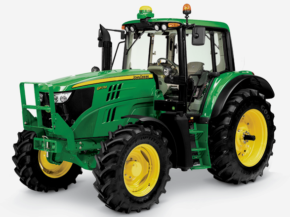 JD 6155M
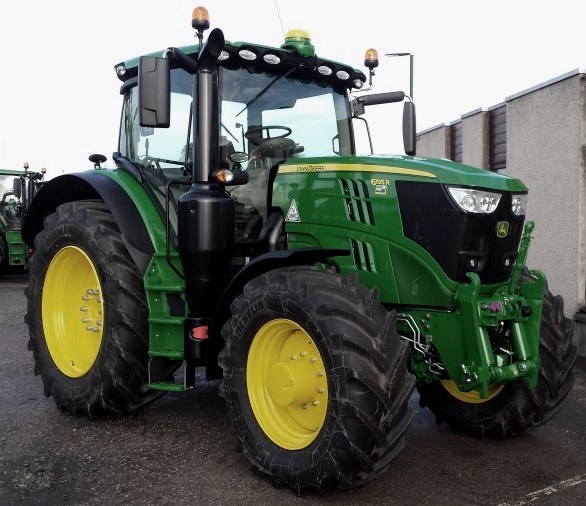 JD 6195R
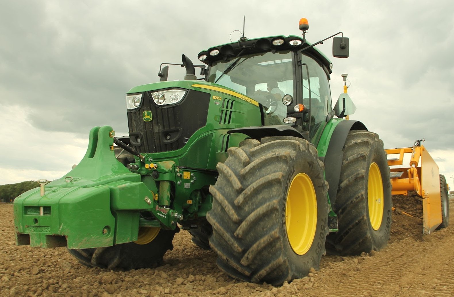 JD 6210R
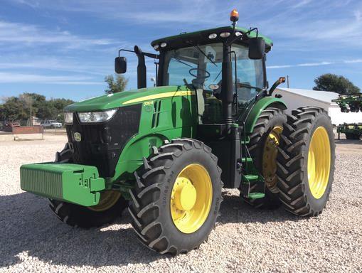 JD 7210R
 JD 7250R
 JD 7310R
 JD 8245R
 JD 8295R
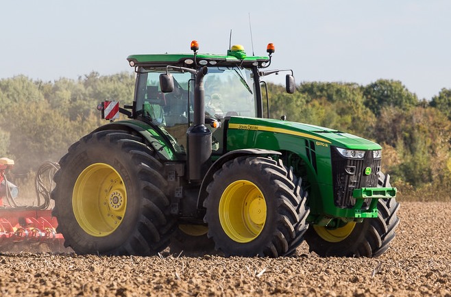 JD 8370R
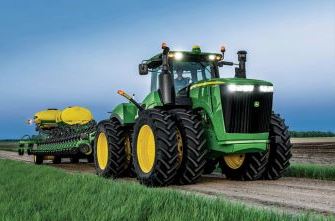 JD 9370R
 120R Loader
 D120 Loader
 H120 Loader
 45 Loader
 200CX Loader
 D160 Loader
 D170 Loader
 H160 Loader
 H165 Loader
 H240 Loader
 210 Loader
 220R Loader
 300E Loader
 300X Loader
 300CX Loader
 JD 9420R
 JD 9510R
 JD GX335
 JD GX85
 JD LA105
 JD 5065M
 JD 5055D
 JD 5115R
 JD 5105M
 JD 6110R
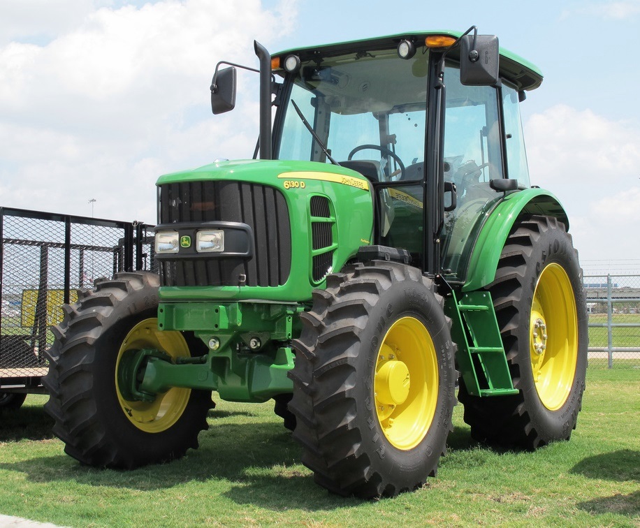 JD 6130D
 JD 6225
 JD 7530
 JD 4044M
 JD 7185J
 300 Loader
 300R Loader
 320R Loader
 400E Loader
 410 Loader
 430 Loader
 460 Loader
 521 Loader
 531 Loader
 541 Loader
 551 Loader
 631 Loader
 651 Loader
 661 Loader
 603R Loader
 JD D130
 JD D160
 JD 325
 JD 335
 JD 345
 JD 2520
 JD 3005
 JD 3720
 JD 1025R
 JD 3033R
 JD 5090EL
 JD 5100MH
 JD 5075GV
 JD 6090RC
 JD 6110B
 623R Loader
 643R Loader
 731 Loader
 746 Loader
 751 Loader
 533 Loader
 583 Loader
 633 Loader
 653 Loader
 683 Loader
 H260 Loader
 663R Loader
 663 Loader
 683R Loader
 753 Loader
 JD 6125J
 JD 6150RH
 JD 6210J
 JD 7195J
 JD 8310
 JD 6325
 JD 5525
 JD 5083EN
 JD 5100GN
 JD 5125R
 210C Backhoe
 300D Backhoe
 310G Backhoe
 410G Backhoe
 710G Backhoe
 80 Loader
 100 Loader
 146 Loader
 148 Loader
 158 Loader
 168 Loader
 175 Loader
 522 Loader
 542 Loader
 540R Loader
 562 Loader
 563 Loader
 673 Loader
 741 Loader
 L108 Automatic
 L120 Automatic
 LA110 Automatic
 LA120 Automatic
 LA150 Automatic
 LT155
LT155 LT160 Automatic
 LT180 Automatic
 LTR180
 X165
X165 E100
E100 E120
E120 E150
E150 LTR166
 LA135
LA135 LA165
LA165 LX277
LX277 LX288
LX288 LX255
LX255 S240
S240 GT235
GT235 G110 Automatic
 JD 3203
 JD 5520
 JD 316
 JD 420
 JD 425
 JD 445
 JD_5050D
 X300
X300 X304
X304 X310
X310 X110 Automatic
 H310 Loader
 H340 Loader
 H360 Loader
 H380 Loader
 H480 Loader
 240 Loader
 245 Loader
 260 Loader
 265 Loader
 600R Loader
 620R Loader
 640R Loader
 660R Loader
 680R Loader
 JD_5039D
 X146R
X146R X360
X360 X155R
X155R X140 Automatic
 X350
X350 X380
X380 X500
X500 X590
X590 X700
X700 3036E
3036E 2038R
2038R 3038R
3038R 4049M
4049M JD 4100
 X738
X738 X740
X740 X748
X748 X749
X749 X950R
X950R JD 4510
 5045D
5045D 5050E
5050E 5060E
5060E 5078E
5078E