
________________________________________________________________________________
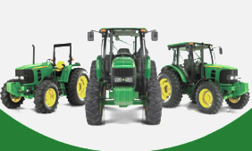
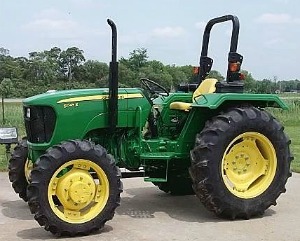
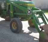
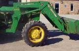
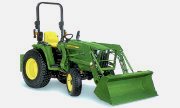
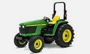
John Deere 5300, 5400, 5500 Hydraulics, Hitch, PTO and Drawbar
- 5300, 5400, 5500 Engine and Drivetrain
- 5300, 5400, 5500 Hydraulics, Hitch, PTO and Drawbar
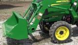
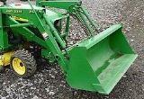
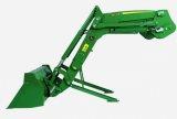
- VIEW 520 LOADER SPECIFICATIONS
- VIEW 540 LOADER SPECIFICATIONS
JD 5500, 5400, 5300
Hydraulic System
Warming Hydraulic System Oil
- Hydraulic system may be slow in function when tractor is started in
cold weather.
- This is because cold oil will not flow easily through the filter
screen or hydraulic system filter.
- Steering is also slow until system warms up.
- Hydraulic system will function normally when oil warms up.
- Start engine and let it run at about 1000 rpm. Turn and hold steering
wheel in full left or right turn.
Remote Hydraulic Cylinders
Use Correct Hose Tips - If John Deere 5300, 5400, 5500 tractor is
equipped with a selective control valve (SCV), the couplers receptacles
accept a standard hose
tip as recommended by ISO1 and SAE2. Adapters are available to allow
connecting the older John Deere hose tips to the ISO couplers on your
tractor.
Control Lever and Coupler Identification
The tractor can be fitted with:
- One double acting valve (located on the left-hand side of the seat)
with a lock function which holds the control lever in the "Raise" or
"Lower" position until it is
moved manually.
- One or two single or double acting valves (located on the left-hand
side of the seat) without lock function.
- Fore-and-aft movement of lever operates the upper right coupler
receptacles.
- Fore-and-aft movement of lever operates the upper left coupler
receptacles (if equipped).
- Fore-and-aft movement of lever operates the lower left coupler
receptacles (if equipped).
Maximum Permissible Oil Withdrawal
To operate large hydraulic cylinders such as those used on tipping
trailers, 10 liters (2.6 U.S. gal.) of oil may be drawn from the
transmission case through the
connecting lines. This figure applies when the oil in the transmission
case is at the minimum mark on the dipstick. If the oil is up to the
maximum mark, a further 5
liters (1.3 U.S. gal.) may be withdrawn.
Never perform heavy jobs such as towing, operating a PTO or driving fast
when withdrawal results in the oil level dropping below the minimum
mark. If required, a
further 10 liters (2.6 U.S. gal.) may be added to the transmission case;
this increases the amount that may be withdrawn accordingly. During oil
withdrawal, the
tractor should not be inclined in any direction by more than 18°. If
5300, 5400, 5500 John Deere tractor is inclined by more than 18°, only a
correspondingly lower
quantity of oil may be withdrawn. For refilling, use only HY-GARD
Transmission and Hydraulic Oil or its equivalent.
Connecting Cylinder Hoses
- Remove dust caps (if equipped) from hose ends. Pull dust plugs from
couplers.
- Make sure hose end and coupler receptacles are clean.
- Check hoses to see which is used for extending cylinder.
- This hose must be connected to coupler receptacle in order to extend
cylinder when SCV levers are moved rearward or inward.
- To connect each hose, push hose tip firmly into coupler receptacle.
- Pull lightly on hose to make sure connection is tight.
Connecting Hose Under Pressure - Implement must be raised slightly, by
pulling back lever to reset coupler check valves, before it can be
lowered. If hoses should
accidentally be disconnected from tractor during use, clean hose tip and
coupler receptacle. Hoses can be reinstalled as previously described
with minimal loss of
oil.
Connecting Single-Acting Cylinder - The volume of oil required to extend
cylinder must not lower transmission- hydraulic oil level below end of
dip- stick. Check oil
level with cylinder fully extended. In order for lever to work properly,
a single-acting cylinder should be connected only to receptacle.
Neutral Lever Position - Spring pressure returns lever to a centered
position. With the control lever in this position, the remote cylinder
is hydraulically locked in
position. When released, levers return automatically to center position
because they do not have a detent position.
Retracting Cylinder - Pull lever from neutral slightly to the rear and
hold it against spring pressure. This retracts cylinder connected to No.
I SCV, II SCV or III SCV
coupler receptacles. When released, levers return automatically to
center position because they do not have a detent position.
Extending Cylinder - Push lever slightly forward and hold it against
spring pressure. This extends cylinder connected to No. I SCV, II SCV or
III SCV coupler
receptacles. When released, levers return automatically to center
position because they do not have a detent position.
Disconnecting Cylinder Hoses
- If possible, retract remote cylinder as much as possible to protect
cylinder rod from damage.
- With as much hydraulic pressure as possible relieved from hoses, pull
hoses from couplers.
- Make sure dust plugs for receptacles and dust caps for hoses are
clean, then reinstall.
Return Line to Sump - For some applications (front loader for example)
it may be necessary to connect the oil return hose to the sump via quick
coupler.
John Deere 5500, 5400, 5300 Power Take-Off
Attaching PTO-Driven Implement
- Turn key off to stop engine.
- If Power Take-Off driven implement will be attached to drawbar, the
drawbar must be positioned so there is 400 mm (15.7 in.) between end of
PTO shaft and
center of drawbar pin hole. Make sure drawbar locking pins and spring
pins are in place. If implement will be connected to three-point hitch,
be sure drawbar will not
interfere. Remove it if necessary.
- There are two holes at the front of the drawbar. Place the drawbar pin
in the second hole for the proper 400 mm (15.7 in.) distance. When using
the first hole, a
distance of 450 mm (17.7 in.) is obtained.
- Attach implement to JD 5300, 5400, 5500 tractor before connecting PTO
drive line. Lock hitch in upward position if it is not to be used.
- Rotate PTO shield upward for clearance. With engine off, turn shaft
slightly by hand if necessary to line up splines. Connect drive line to
PTO shaft. Pull out on
shaft to be sure drive line is locked to PTO shaft. Place PTO shield in
downward position.
- Be sure all shields are in place and in good condition. Never operate
PTO unless master shield is properly installed. WITH ENGINE STOPPED,
check integral
shields on drive line by making sure they rotate freely on shaft.
Lubricate or repair as necessary.
- Check carefully for any interference, make sure hitch is locked in the
up position if it is not used.
Operating Tractor Power Take-Off at Correct Speed
Engine will not start if PTO clutch lever is engaged.
- Start engine and push hand throttle lever forward until tachometer
indicates PTO rated speed of 2100 rpm for standard 540 and 1000
operation or 1500 rpm for
540E operation.
- Select the PTO speed if the John Deere 5300, 5400, 5500 tractor is
equipped with 540 and 540E or 540 and 1000 PTO option. Move lever
forward for 540 or
rearward for 540E or 1000 operation. Position is neutral. This lever is
on the rear of the gearbox. If dual speed PTO is not provided, this
lever will not be installed.
The PTO speed selector lever must only be used when no equipment is
connected to the PTO.
- Make sure that lever on the left fender is in rear position
(independent PTO operation) 1.
- Move control lever inward and forward to engage PTO. PTO indicator
will light when PTO is engaged.
- Pull control lever back to disengage Power Take-Off.
- For ground speed PTO operation move lever 1 forward. In this case, PTO
engagement is independent from position of control lever.
Adjusting PTO Clutch Operating Rod
- Remove clip pin from forward end of PTO clutch lever. Loosen lock nut
from rear of front clevis.
- Adjust length of rod so the clip pin can be inserted with the rod
pulled forward and the arm pulled rearward to eliminate freeplay.
- Lengthen rod by 1/2 turn of the clevis to provide a slight amount of
lever freeplay.
- Reinstall clip pin in clevis and arm. Check for equal thread
engagement at each end of the PTO clutch rod.
- Lock nut at the rear (not shown) can be loosened and the rod turned to
equalize thread engagement (Power Take-Off adjustment is not affected).
- Retighten lock nuts at each end of rod.
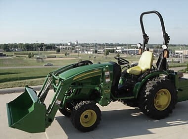
JD 5300, 5400, 5500 Three-Point Hitch
Rockshaft Control Levers
- The rockshaft position is controlled by two levers, the position
control lever and the draft control lever.
- The position control lever raises the hitch when pulled rearward and
lowers the hitch when moved forward.
- The draft control lever controls hitch position relative to draft
loads.
Using Rockshaft Position Control - Move draft control lever forward when
you dont want rockshaft to adjust automatically to draft load, such as
attaching implement
to tractor. Use position control lever to control hitch movement and
depth.
Position control should be used for the following applications:
TRANSPORT of implements and end of field turn-around. Position control
lever should be moved fully
rearwardfor transport for both load and non-load sensing usage. CONSTANT
DEPTH of implements on level terrain and for non-ground engaging
implements such
as spreaders or sprayers. Place position control lever at depth desired.
FLOAT operation for implements with skids or depth gauge wheels designed
to carry full
implement weight. Push both levers all the way forward so implement can
follow the ground contour.
Position Control Lever Stop - For convenience, set adjustable depth.
Operate implement a few minutes to determine proper height, then unscrew
ring nut. Move
stop up against lever, and lock stop in position by tightening ring nut.
Rockshaft will then lower to same position each time lever is pushed
forward to stop.
Using Draft Control - The rockshaft is equipped with a variable draft
control system.
Use draft load sensing when:
- Operating with a fully mounted implement in hilly and swale terrain.
The implement will raise and lower to follow the ground contours while
maintaining a nearly
constant depth.
- Operating in varying soil conditions. The implement is raised slightly
to get through tough spots so you do not have to shift to a lower gear.
Draft control lever controls amount of load required before hitch
responds. With lever moved fully forward to the position marked "off",
there is no draft sensing.
Placing the lever toward the rear position reduces the amount of draft
load required to override the position setting set by the position
control lever and raise the
rockshaft. Draft sensitivity ranges can be changed by repositioning the
center link. For draft load sensing operation, initially move position
control lever in its fully
forward position and the draft control lever in the fully rearward
(least draft) position.
Then, with 5400, 5300, 5500 John Deere tractor moving, push the draft
control lever forward to increase the load to the desired setting. Pull
control lever rearward to
set maximum depth of implement. Set position control lever stop so
control lever can be brought back to the same position each time. The
maximum depth will
prevent the rockshaft from lowering all the way when the tractor begins
to slip. The position control lever can also be raised slightly to
override the draft control
setting to help get through slippery spots without getting stuck. The
position control lever can be moved fully rearward to raise the hitch at
the end of the field.
Adjusting Rockshaft Rate-of-Drop - Turn rockshaft rate-of-drop adjusting
knob clockwise to slow down rockshaft drop. Turn counterclockwise to
increase rate-of-drop.
Converting Category 2 Hitch to Category 1 - Tractor center link and
draft link ends are sized for Category II implement attaching pins. If
Category 1 implements are
to be used, the Category 2 hitch can be converted to Category 1 by
inserting bushing to reduce the size of the center link end and using
the smaller pin through the
implement mast, and by adding bushings to end of draft links.
Positioning Center Link
The center link attaching bracket has holes which allow three different
positions for attaching the center link. The position effects the draft
sensing sensitivity.
Move the center link attachment to holes if: Excessive hitch activity or
hunting occurs in draft control operation. The rear of the implement
raises too much when
lifted. The implement weight which can be lifted is reduced slightly
with the center link attached in the lower holes. The draft control
lever range is too small.
Move the center link attachment to holes if: The hitch seems
unresponsive in draft control operation and allows the engine speed to
drop too far before raising the
rockshaft. The rear of the implement droops and drags the ground as the
implement is lifted.
Attaching Implements to 3-Point Hitch
- Be sure drawbar will not interfere. If necessary, move drawbar ahead
or remove it. Check for any other potential interference.
- Back John Deere 5300, 5400, 5500 tractor up to implement so that hitch
points are in line. Engage parking brake and stop the engine before
leaving the tractor's
seat.
- Slip draft links over implement hitch pins, and retain with quick-lock
pins.
- Locking pins can be stored on draft links when not in use.
Quick-Coupling (Hook-Type) Draft Links - These draft links are intended
for Category I and Category II implements. Implements can be attached to
and removed
from the draft links without the driver having to leave his seat.
Attaching implement
- Adjust draft links to the dimension of implements by means of
adjusting rod (if equipped).
- With draft links lowered, reverse tractor until the coupler hooks are
below the implement hitch pins.
- Make absolutely certain that implement is correctly locked to coupler
hooks.
- Slowly raise draft links until pins are engaged in coupler hooks and
locked into position.
- Adjust center link to the required length and attach to top attaching
point of implement mast.
- To remove center link from transport hook, lift center link locking
clip.
- Attach center link to implement top mast. Adjust center link and lift
links as necessary.
- Using position control lever, lower and raise implement slowly and
check for any point of interference.
Leveling the John Deere 5400, 5300, 5500 Hitch
- Lower implement to take weight off hitch.
- Adjust center link to level implement front-to-rear: Unlatch locking
clip. Loosen ring nut. Rotate center link body clockwise to lengthen
center link or
counterclockwise to shorten it. Length of link must be kept within the
following limits (measured at the center link ends): min. length = 530
mm (20.87 in) / max.
length = 730 mm (28.74 in).
- Maximum adjustment range of the center link can only be obtained if
the ends are positioned equally within the body when attached to an
implement.
- After the adjustment is completed, tighten ring nut. Re-latch the
locking clip if link is not in use.
- Adjusting right-hand or left-hand link to level implement side to
side: Loosen nut, turn crank handle clockwise to raise draft link, turn
crank handlecounterclockwise
to lower draft link.
- After adjustment, tighten nut onto the lower body to prevent change of
adjustment during operation. Length of links must be kept within the
following limits:
minimum length 500 mm (19.7 in.) / maximum length 670 mm (26.4 in.).
Adjusting Rockshaft Control Lever Friction - If rockshaft position
control lever or draft control lever do not stay in set position,
increase relevant lever friction by
tightening draft control lever bolt and/or position control lever bolt
until the desired friction is obtained.
Selecting Drawbar Position - For drawn PTO-driven implements, drawbar
must be in the short position (as shown) to provide 400 mm (15.7 in.)
between drawbar
hitch hole and end of PTO shaft. For maximum traction and efficiency,
drawbar should be positioned in the center, short position.
Adjusting John Deere 5300, 5400, 5500 Drawbar Length - Remove pin and
drawbar pin. Slide drawbar to desired position. Re-install drawbar pin
and insert pin.
Using Swinging Drawbar - Drawbar pins can be removed to let drawbar
swing freely. This is helpful when turning under load.
Height Adjustable Trailer Hitches - These hitches can be adjusted up or
down according to the implement height and to obtain clearance for the
center link or PTO
operation. Depending on legal requirements in the different countries,
hitches of EEC or CUNA type are available.
Adjusting Hitch Height
- To adjust hitch height, remove locking pin on each side.
- Support hitch safely and remove side pins.
- Move hitch to the required position, re-install side pins, remove
support and install locking pins.
Adjusting Sliding Hitch Height
- Support hitch with one hand and with the other hand pull quick release
lever to the right.
- Move hitch to the required position and push the quick release lever
to the left and down to lock it.
- Make sure that the side locking pins have fully engaged in the side
support slots.
- If necessary, hitch can be completely removed by pulling the end
stroke plate.
Pick-Up Hitch
This type of hitch is operated via the rockshaft and a bowden cable.
Attaching an Implement
- From the operator's seat, raise the draft links fully using position
control lever. Pull handle firmly to unlatch the hitching mechanism.
- While the handle is still pulled (latching hooks disengaged) lower
three-point hitch to the desired position. Release handle.
- Reverse the JD 5300, 5400, 5500 tractor carefully, making sure that
the hook does not dig into the soil.
- Before hitching up the implement, make sure the latching hooks have
been returned to their engaged position by spring force.
- Raise the draft links (and thus the pick-up hitch) so that the hook
engages in the towing eye of the implement.
- Continue raising until the bottom frame locks in position behind the
locking hooks.
- Lower the draft links so that the weight of the implement and bottom
frame is supported by the hitch frame and not by the lift arms.
- Make sure that the implement is hitched correctly and locked securely.
Hook/Drawbar
- It is possible to replace the hook of the pickup hitch with a drawbar.
- To do this, proceed as described previously under points 1 to 4, then
SHUT OFF the tractor engine, and change the hook or drawbar.
- Take care to re-install all securing pins and inspect hitch pivots for
obstructions.
- If necessary, the drawbar can be swung to the side by moving the
appropriate securing pin when the drawbar is being installed or when the
hitch is unlatched.
- Make sure that the drawbar is not free to swing within the sub-frame
while in use, and always operate the tractor with care when towing
offset trailed equipment so
that the tractor does not become unstable and turn over.
- It is possible to adjust the drawbar to two different lengths to suit
PTO-driven equipment. Dont use the extended position to tow heavy
weights.
________________________________________________________________________________
________________________________________________________________________________________
 JD SPECS
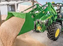 JD LOADERS
 JD MAINTENANCE
 JD INSTRUCTIONS
 JD PROBLEMS
________________________________________________________________________________________
 JD 2025R
 JD 3039R
 JD 4044R
 JD 4105
 JD 4720
________________________________________________________________________________________
 420 Loader
 419 Loader
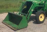 510 Loader
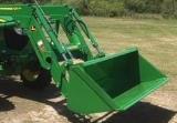 512 Loader
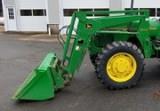 520 Loader
________________________________________________________________________________________
 520M Loader
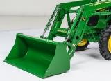 540M NSL
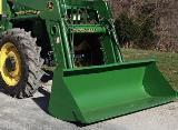 540 Loader
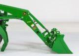 440R Loader
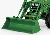 H180 Loader
________________________________________________________________________________________
________________________________________________________________________________________
 JD 5045E
 JD 5085E
 JD 5100M
 JD 6105R
 JD 6120M
________________________________________________________________________________________
 JD 6155M
 JD 6195R
 JD 6210R
 JD 7210R
 JD 7250R
________________________________________________________________________________________
 JD 7310R
 JD 8245R
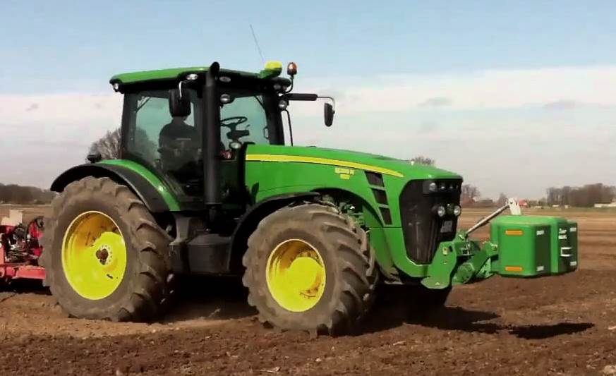 JD 8295R
 JD 8370R
 JD 9370R
________________________________________________________________________________________
 120R Loader
 D120 Loader
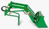 H120 Loader
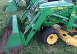 45 Loader
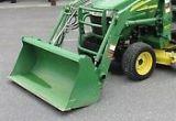 200CX Loader
________________________________________________________________________________________
 D160 Loader
 D170 Loader
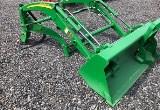 H160 Loader
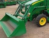 H165 Loader
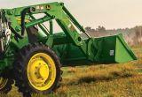 H240 Loader
________________________________________________________________________________________
 210 Loader
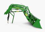 220R Loader
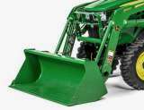 300E Loader
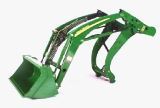 300X Loader
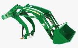 300CX Loader
________________________________________________________________________________________
 JD 9420R
 JD 9510R
 JD GX335
 JD GX85
 JD LA105
________________________________________________________________________________________
 JD 5065M
 JD 5055D
 JD 5115R
 JD 5105M
 JD 6110R
________________________________________________________________________________________
 JD 6130D
 JD 6225
 JD 7530
 JD 4044M
 JD 7185J
________________________________________________________________________________________
 300 Loader
 300R Loader
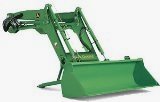 320R Loader
 400E Loader
 410 Loader
________________________________________________________________________________________
 430 Loader
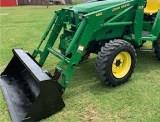 460 Loader
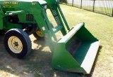 521 Loader
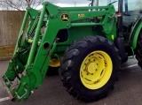 531 Loader
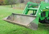 541 Loader
________________________________________________________________________________________
 551 Loader
 631 Loader
 651 Loader
 661 Loader
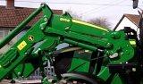 603R Loader
________________________________________________________________________________________
 JD D130
 JD D160
 JD 325
 JD 335
 JD 345
________________________________________________________________________________________
 JD 2520
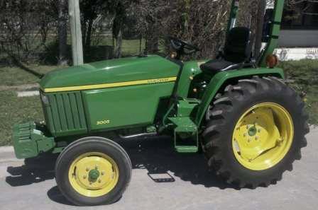 JD 3005
 JD 3720
 JD 1025R
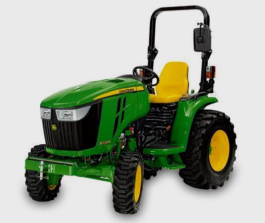 JD 3033R
________________________________________________________________________________________
 JD 5090EL
 JD 5100MH
 JD 5075GV
 JD 6090RC
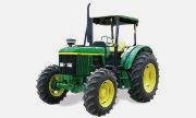 JD 6110B
________________________________________________________________________________________
 623R Loader
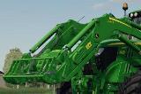 643R Loader
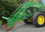 731 Loader
 746 Loader
 751 Loader
________________________________________________________________________________________
 533 Loader
 583 Loader
 633 Loader
 653 Loader
 683 Loader
________________________________________________________________________________________
 H260 Loader
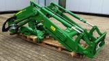 663R Loader
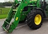 663 Loader
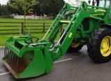 683R Loader
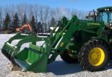 753 Loader
________________________________________________________________________________________
 JD 6125J
 JD 6150RH
 JD 6210J
 JD 7195J
 JD 8310
________________________________________________________________________________________
 JD 6325
 JD 5525
 JD 5083EN
 JD 5100GN
 JD 5125R
________________________________________________________________________________________
 210C Backhoe
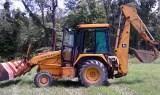 300D Backhoe
 310G Backhoe
 410G Backhoe
 710G Backhoe
________________________________________________________________________________________
 80 Loader
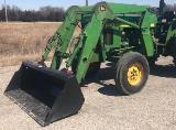 100 Loader
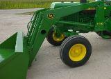 146 Loader
 148 Loader
 158 Loader
________________________________________________________________________________________
 168 Loader
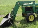 175 Loader
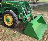 522 Loader
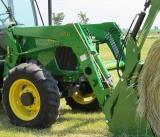 542 Loader
 540R Loader
________________________________________________________________________________________
 562 Loader
 563 Loader
 673 Loader
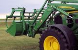 741 Loader
________________________________________________________________________________________
 L108 Automatic
 L120 Automatic
 LA110 Automatic
 LA120 Automatic
 LA150 Automatic
________________________________________________________________________________________
 LT155
LT155 LT160 Automatic
 LT180 Automatic
 LTR180
 X165
X165________________________________________________________________________________________
 E100
E100 E120
E120 E150
E150 LTR166
________________________________________________________________________________________
 LA135
LA135 LA165
LA165 LX277
LX277 LX288
LX288 LX255
LX255________________________________________________________________________________________
 S240
S240 GT235
GT235 G110 Automatic
 JD 3203
 JD 5520
________________________________________________________________________________________
 JD 316
 JD 420
 JD 425
 JD 445
________________________________________________________________________________________
 JD_5050D
 X300
X300 X304
X304 X310
X310 X110 Automatic
________________________________________________________________________________________
 H310 Loader
 H340 Loader
 H360 Loader
 H380 Loader
 H480 Loader
________________________________________________________________________________________
 240 Loader
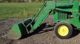 245 Loader
 260 Loader
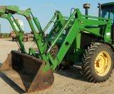 265 Loader
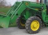 280 Loader
________________________________________________________________________________________
 600R Loader
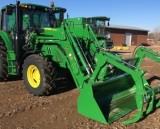 620R Loader
 640R Loader
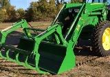 660R Loader
 680R Loader
________________________________________________________________________________________
 JD_5039D
 X146R
X146R X360
X360 X155R
X155R X140 Automatic
________________________________________________________________________________________
 X350
X350 X380
X380 X500
X500 X590
X590 X700
X700________________________________________________________________________________________
 3036E
3036E 2038R
2038R 3038R
3038R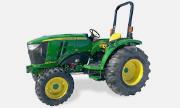 4049M
4049M JD 4100
________________________________________________________________________________________
 X738
X738 X740
X740 X748
X748 X749
X749 X950R
X950R________________________________________________________________________________________
 JD 4510
 5045D
5045D 5050E
5050E 5060E
5060E 5078E
5078E