
________________________________________________________________________________
PTO clutch Massey Ferguson tractors
- MF 3000-3100 Service and Repair
- MF 5400-5600 Service and Repair
- MF 6100-6200 Service and Repair
- MF 6400-6600 Service and Repair
- MF 7400-7700 Service and Repair
The power take-off PTO clutch, fitted at the front of the rear axle
housing, is driven by a splined shaft located inside the engine clutch
input shaft, which rotates integral with the engine flywheel. The PTO
clutch control shaft traverses: the gearbox primary shaft, the
Speedshift, the reverse shuttle and the intermediate shaft.
The MF 3060/3070/3090 tractor clutch consists
of:
- a unit (9), supported by two ball bearings (2) (7) separated by a
sleeve (4) centred in a bore of the centre housing. The sleeve (27)
supports the ball bearing (22), the drive hub (21) and the piston (10).
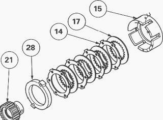
- a bell (15) including a set of discs (17) and intermediate plates (14)
is fixed onto the unit. The unit (9) comprises external helical teeth
that drive the hydraulic pump gear. The bearings and discs are
lubricated. Depending on the model, the clutch has either 4 or 5 discs.
On the 4-disc version (Fig.1), a special spacer (28) is fitted in place
of the missing disc and spacer.
Clutch engaged position
A 17 bar hydraulic system supplies the clutch via a PTO proportional
solenoid valve located on the right-hand hydraulic cover plate. Oil
enters the unit (9) via channels a and c and chamber b. It pushes the
piston (10) which compresses the discs (17) against the intermediate
plates (14).
As the intermediate plates are attached to the bell (15) by lugs and the
discs (17) are attached to the hub (21), the drive is transmitted to the
drive hub (21) in which the intermediate shaft controlling the PTO
driving gear is located.
At the same time, the pressure acting on the PTO brake piston is cut,
allowing the 540 and 1000 rpm gears of the PTO lower shaftline to turn
freely. When engaging the clutch, the discs are cooled and lubricated.
PTO brake position
When the supply is cut, the spring (18) pushes the piston back against
the unit (9). When the knob located in the cab is in the PTO brake
position, the ON/OFF solenoid
valve for the PTO brake directs the oil towards the top cover plate,
which is fitted at the rear of the tractor.
Pressure acts on a piston that pushes the bearing cup on the rear
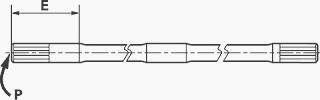
bearing cone, progressively immobilising the driving gear. Fit the
longer end "E" or the paint mark "P"
on the clutch control shaft so that it is facing towards the input
housing (Fig.71).
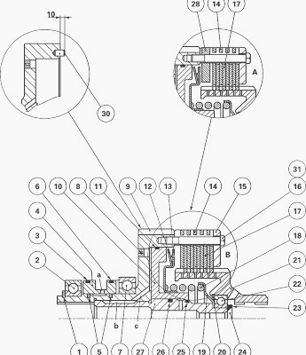
Fig.72. Parts list
(1) Circlip, (2) Bearing, (3) "O" ring, (4) Sleeve, (5) Seal rings, (6)
"O" ring, (7) Bearing, (8) Valve, (9) Clutch unit, (10) Piston, (11) "O"
ring, (12) Belleville progressivity washers, (13) Support, (14)
Intermediate plates A: 4-disc clutch B: 5-disc clutch, (15) Bell, (16)
Screw, (17) Discs, (18) Spring, (19) Spring seat, (20) Snap ring, (21)
Drive hub, (22) Bearing, (23) Washer, (24) Screw (25) "O" ring, (26) "O"
ring, (27) Sleeve, (28) Special spacer (4-disc version only), (30) Pins,
(31) Treated washers

Removing and refitting the PTO clutch
(2-speed version)
Remove the right-hand hydraulic cover plate.
Remove the PTO top cover plate located at the rear of the MF
3060/3070/3090 tractor, the driving gear and the intermediate Shaft.
Take off the retaining screw (3) from the clutch (1) using a combination
wrench (for cutting and shaping as needed). Remove the latter and the
spring (5).
Check and clean the components. Replace any defective parts.
Check that the "O" rings (2) and (4) are not damaged.
Install the spring (5) in the port of the PTO shaft and refit the clutch
(1) by moving it fully forwards using a lever to compress the spring in
order to fit the screw (3).
Clean and smear the screw (3) with Loctite 542 and tighten to 50 - 70
Nm.
Install the intermediate shaft, the driving gear and the top cover
plate.
Install the right-hand hydraulic cover plate.
Check for the correct operation of the clutch, PTO brake and linkage.
Check tightness:
- of the mating faces (spool valve support, top cover plate, right-hand
hydraulic cover plate)
- Hydraulic unions
Removing and refitting the Massey
Ferguson 3060/3070/3090 tractor PTO clutch (4-speed version)
On 4-speed version tractors (economy), removal of the PTO clutch is the
same as the 2-speed version.
The only difference relates to the parts to be removed for access (i.e.
driving gears and intermediate shaft).
Remove the right-hand hydraulic cover plate.
Remove the PTO top cover plate located at the rear of the tractor, the
driving gear and the intermediate shaft.
Take off the retaining screw (3) of the clutch using the same equipment
as that used for the 2-speed version. Remove clutch and spring (5).
Check and clean the components. Replace any defective parts.
Check that the "O" rings (2) and (4) are not damaged.
Place spring (5) in the port of the PTO shaft and refit the clutch (1)
by moving it fully forwards using a lever to compress the spring in
order to fit the screw (3).
Clean and smear the screw with Loctite 542 and tighten to 50 - 70 Nm.
Install the intermediate shaft, the driving gear and the rear cover
plate.
Install the right-hand hydraulic cover plate.
Check correct operation of the clutch and power take-off brake.
Check tightness:
- of the mating faces (spool valve support, top cover plate, right-hand
hydraulic cover plate)
- Hydraulic unions
Disassembling and reassembling the
Massey Ferguson 3060/3070/3090 tractor clutch
Take off the screws (16) and washers (31).
Remove the bell (15), discs (17) and intermediate plates (14).
Place the clutch unit (9) into a vice equipped with protective jaws.
Remove the "O" rings (3) (6).
Remove the circlip (1).
Extract the bearing (2) with the sleeve (4).
Take off the seal rings (5) and extract the bearing (7)
Hold the spring (18) using a makeshift tool (Fig.3).
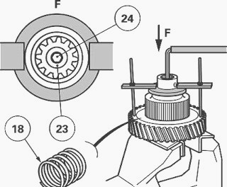
Take off the screw (24) and remove the washer (23) (Fig.3). Gradually
decompress the spring using the tool.
Remove the drive hub (21), the spring seat (19), the spring (18), the
support (13) and the Belleville washer (12).
Take off the snap ring (20).
Extract the bearing (22).
Take out the piston (10) by hitting the clutch unit on a block of wood.
Take off the "O" rings (11) (25) (26).
The valve (8) is crimped onto the clutch unit (9). Check that the
bearing moves freely by rapidly shaking the unit up and down several
times. The sleeve (27), smeared with Loctite 648, is fitted using the
press. If disassembly is necessary, make sure that there is no Loctite
blocking the channel when reassembling. Two pins (30) are fitted in the
unit (9) 10 mm from the face.
Check and clean the components and replace those that are defective.
Using a suitable fixture and a press, fit the bearing (7) home against
the shoulder.
Place seal rings (5) into their grooves and hook their ends, making sure
that they turn freely.
Slide the sleeve (4) over the rings and avoid damaging them. Turn the
larger sleeve diameter towards the bearing (7).
Using a suitable fixture and a press, fit the bearing (2) up against the
shoulder of the unit (9).
Position the circlip (1).
Replace and lubricate the "O" rings (11) (25) (26).
Lubricate the sleeve (27) and the piston (10) and fit it into the unit
using a plastic hammer.
Using a suitable fixture and a press, fit the bearing (22) into the hub
(21) and refit the snap ring (20).
Install the Belleville washer (12), the support (13), the spring (18),
the spring seat (19) and the drive hub (21).
Compress the spring (18) with the tool (Fig.3), fit the washer (23) and
tighten the screw (24) smeared with Loctite 270 to a torque of 24 - 28
Nm.
Position the spacer (if fitted), intermediate plates and discs on the
hub (21).
Position the bell (15) in the two pins (30). Fit the screws (16) each
fitted with a washer (31), lightly smeared with Loctite 270, and tighten
to 15 - 18 Nm.
Manually check that the discs and intermediate plates are not obstructed
in any way.
Lubricate and fit the "O" rings (3) (6). The rings have different
diameters. Install the clutch.
________________________________________________________________________________
________________________________________________________________________________________
 SPECS
SPECS LOADERS
 MAINTENANCE
 PROBLEMS
________________________________________________________________________________________
 MF 1523
 MF 1531
 MF 135
 MF 1547
 MF 1635
________________________________________________________________________________________
________________________________________________________________________________________
 231
231 231S
231S 235
235 240
240 241
241________________________________________________________________________________________
 255
255 265
265 274
274 285
285 375
375________________________________________________________________________________________
________________________________________________________________________________________
 916X Loader
 921X Loader
 926X Loader
 931X Loader
 936X Loader
________________________________________________________________________________________
 941X Loader
 946X Loader
 951X Loader
 956X Loader
 988 Loader
________________________________________________________________________________________
 1655
1655 GS1705
 1742
1742 2635
2635 4608
4608________________________________________________________________________________________
 1080
1080 1100
1100 2615
2615 3050
3050 3060
3060________________________________________________________________________________________
 4708
4708 5455
5455 5450
5450 5610
5610 5613
5613________________________________________________________________________________________
 DL95 Loader
 DL100 Loader
 DL120 Loader
 DL125 Loader
 DL130 Loader
________________________________________________________________________________________
 DL135 Loader
 DL250 Loader
 DL260 Loader
 L90 Loader
 L100 Loader
________________________________________________________________________________________
 6499
6499 7480
7480 7618
7618 7726
7726 1533
1533________________________________________________________________________________________
 2604H
2604H 2607H
2607H 4455
4455 4610M
4610M 4710
4710________________________________________________________________________________________
 L105E Loader
 L210 Loader
 1014 Loader
 1016 Loader
 1462 Loader
________________________________________________________________________________________
 1525 Loader
 1530 Loader
 232 Loader
 838 Loader
 848 Loader
________________________________________________________________________________________
 5712SL
 6713
6713 6715S
6715S 7475
7475 7615
7615________________________________________________________________________________________
 7716
7716 7724
7724 8240
8240 8650
8650 8732
8732________________________________________________________________________________________
 246 Loader
 1036 Loader
 1038 Loader
 1080 Loader
 856 Loader