________________________________________________________________________________
Kawasaki FH721V Carburetor
Kawasaki FH721V - Fuel and Air Flow
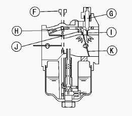
The pilot system includes the pilot jet F, pilot screw G (Idle mixture
screw), pilot air jet H, pilot outlet I, and the bypass holes J. The
pilot system meters the fuel/air mixture while the engine is idling and
running under a light load. Under these conditions there is very little
air flow through the carburetor bore; so little that it is not enough to
draw fuel through the main system of the carburetor and atomize it.
Instead, the fuel is drawn through the pilot system, since the nearly
closed throttle valve K causes high speed air flow past the pilot outlet
and bypass holes (even at low engine speed). Fuel flow in the pilot
system is metered by the pilot jet. Air for better atomization is
admitted via the pilot air jet in the mouth of the carburetor. The
fuel/air mixture passes into the bore of the carburetor side stream of
the throttle valve through the bypass holes and pilot outlet.
While the throttle valve is almost closed, it covers the small bypass
holes opening into the bore from the pilot system. As the throttle valve
begins to open, it uncovers the bypass holes, allowing more fuel/air
mixture to flow. The extra flow is needed because the engine starts to
run faster as the throttle is opened.
The pilot screw controls the amount of fuel/air mixture allowed through
the pilot outlet, but does not meter the bypass holes. A moderate amount
of air comes in around the throttle valve at an idle, so adjusting the
pilot screw changes the fuel/air ratio. Turning the pilot screw (Idle
mixture screw) out (Counterclockwise) enrichens the mixture; turning it
in (clockwise) leans the mixture.
Kawasaki FH721V Carburetor Adjustment
Low Idle Speed Adjustment
- Disconnect all possible external loads from the engine.
- Start the engine and warm it up thoroughly.
- Adjust the low idle speed screw with Phillips Screwedriver until the
engine idles at specified speed.
- Idle Speed (Carburetor idle rpm) - 1450 rpm.
- Release the throttle lever and adjust the low idle speed set screw on
the control plate to obtain the specified governed low idle speed.
- Low Idle Speed (Governed idle rpm) - 1550 rpm.
High Idle Speed Adjustment
- High idle speed adjustment should be made after the idle speed
adjustment is performed.
- Do not adjust high idle speed with the air cleaner removed.
- Start and warm up the engine thoroughly.
- Move the throttle lever at a dash to the high idle position and match
the lever hole position with the panel hole by inserting 6 mm dia., pin
or bolt.
- Loosen two M6 control panel mounting bolts enough to move the control
panel assembly.
- Carefully move the control panel assembly right side up or down to
obtain the specified high idle speed. High Idle Speed 3600 rpm.
- Tighten the M6 Mounting bolts. Torque - Control Panel Mounting Bolts:
5.9 Nm (52 in-lb).
- Remove the 6 mm dia., pin or bolt.
- Check the idle speed, and readjust the idle speed if necessary.
High Altitude Operation
- At high altitude, the standard carburetor air-fuel mixture will be
excessively rich.
- Performance will decrease, and fuel consumption will increase.
- High altitude performance can be improved by installing a smaller
diameter main-jet in the carburetor and correct idle speed.
- The main jet high altitude kits are available if the equipment is to
be used in the high altitudes.
- The main jet numbers are stamped on ends of the main jets.
High Altitude Main Jet
Altitude 0-1000 m (0-3000 ft): Main Jet L: #136; R: #140.
Altitude 1000-2000 m (3000-6000 ft): Main Jet L: #133; R: #139.
Altitude 2000 m (6000 ft): Main Jet L: #130; R: #134.
Kawasaki FH721V Carburetor Disassembly and
Assembly
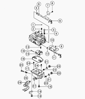
1. Pilot Screw Plug, 2. Pilot Screw, 3. Low Idle Speed Screw, 4. Spring,
5. Seal, 6. Collar, 7. Throttle Valve, 8. Screws, 9. Throttle Shaft, 10.
Choke Valve, 11. Choke Shaft, 12. Seal, 13. Float Valve, 14. Pin, 15.
Float, 16. Gasket, 17. Float Chamber, 18. Screw, 19. Clamp, 20. Plug
Main Jet, 21. Gasket, 22. Main Jet L, 23. Main Jet R, 24. Slow Jet, 25.
Drain Screw, 26. Spring, 27. Gasket, 28. Solenoid Valve
Before disassembly, mark the out side of choke valve and throttle valves
for assembling them. Replace the pilot screw (2) in accordance with the
following procedure if necessary. Remove the pilot screw plug (material:
Stainless steel) as follows: Punch a hole in the plug and pry it out
with an awl or other suitable tool.
Turn in the pilot screw and count the number of turns until it seats
fully but not tightly, and then remove the screw. This is to set the
screw to its original position when assembling. Turn in the new pilot
screw (2) fully but not tightly, and then back it out the same number of
turns counted during disassembly.
Install a new pilot screw plug (1) in the pilot screw hole by pressing
with the rod, and apply a small amount of a bonding agent to the
circumference of the plug to fix the plug. Install the choke valve and
throttle valve on the shaft as the out side mark of them facing out
side, and apply a small amount of a bonding agent to the valve screw
threads. Drive the float pin so that it’s big diameter side faces the
throttle shaft lever side. The fuel inlet valve seat is pressed into the
carburetor body and is not replacable. Assemble carburetor parts which
recommended tightening torque.
Kawasaki FH721V Carburetor Cleaning
- Disassemble the carburetor.
- Immerse all the carburetor metal parts in a carburetor cleaning
solution and clean them.
- Rinse the parts in water and dry them with compressed air.
- Do not use rags or paper to dry parts. Lint may plug the holes or
passages.
- Blow air through the holes and fuel passages with the compressed air.
- All holes must be open. Assemble the carburetor.
Kawasaki FH721V - Fuel system Inspection
- Remove the air cleaner.
- Place a suitable container under the drain screw on the carburetor.
- Turn out the drain screw a few turns to drain the carburetor and check
to see if water or dirt has accumulated in the carburetor.
- Tighten the drain screw. Torque - 2.0 Nm (18 in-lb).
- If any water or dirt is found, clean the carburetor, and fuel tank,
and check the fuel filter.
________________________________________________________________________________
________________________________________________________________________________________
| KOHLER ENGINES SPECS AND SERVICE DATA |
 CH12.5
 CH14S
CH14S CH15S
CH15S CH16
CH16 CH18S
CH18S________________________________________________________________________________________
 CH23S
CH23S CH25S
CH25S CH640S
 CH730S
 CH750S
________________________________________________________________________________________
________________________________________________________________________________________
 CV15S
CV15S CV16S
CV16S CV18S
CV18S CV20S
CV20S CV22S
CV22S________________________________________________________________________________________
 CV23S
CV23S CV25S
CV25S CV490S
 CV491S
 CV730S
________________________________________________________________________________________
 CV740S
 K161
K161 K181
K181 K241
K241 K301
K301________________________________________________________________________________________
 K321
K321 K341
K341 K361
K361 M18
M18 M20
M20________________________________________________________________________________________
 SV470S
 SV530S
 SV540S
 SV590S
 SV600S
________________________________________________________________________________________
 SV710
SV710 SV715
SV715 SV725S
 SV730S
 SV735
SV735________________________________________________________________________________________
| KAWASAKI ENGINES SPECS AND SERVICE DATA |
 FA210
FA210 FA210D
 FB460V
 FC150V
 FC290V
________________________________________________________________________________________
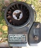 FC420V
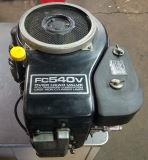 FC540V
 FD501V
 FD590V
 FD620D
________________________________________________________________________________________
 FD731V
 FD750D
 FH430V
 FH500V
 FH531V
________________________________________________________________________________________
 FH580V
 FH601V
 FH680V
 FS541V
 FS600V
________________________________________________________________________________________
 FS651V
 FX651V
 FX691V
 FX730V
________________________________________________________________________________________
 FH541V
 FH641V
 FH661V
 FH721V
 FS730V
________________________________________________________________________________________
| BRIGGS AND STRATTON ENGINES SPECIFICATIONS |
 252707
 253707
 282707
 286707
 303777
________________________________________________________________________________________
 28N707
 28M707
 28Q777
 28R707
 28S777
________________________________________________________________________________________
 311707
 31A607
 31C707
 31N707
 31Q777
________________________________________________________________________________________
 31R977
 31R777
 31P777
 31P977
 350777
________________________________________________________________________________________
 402707
 422707
 42A707
 331777
 331877
________________________________________________________________________________________
| HONDA ENGINES SPECS AND SERVICE DATA |
 G50
G50 G100
G100 GC135
GC135 GC160
GC160 GC190
GC190________________________________________________________________________________________
 GS190
GS190 GX100
GX100 GX120
GX120 GX160
GX160 GX200
GX200________________________________________________________________________________________
 GXV120
 GXV160
 GXV270
 GXV340
 GXV390
________________________________________________________________________________________
 GXV610
 GCV520
 GCV530
 GXV620
 GXV630
________________________________________________________________________________________
 GCV145
 GCV160
 GCV170
 GCV190
 GCV200
________________________________________________________________________________________
 GSV190
 GX110
GX110 GX140
GX140 GV100
GV100 GXV140
________________________________________________________________________________________