________________________________________________________________________________
Onan B43G Carburetor
Onan B43G Carburetor Overhaul
Onan B43G carburetor problems that are not corrected by mixture
adjustments are usually a result of gummed-up fuel passages or worn
internal parts. The most effective solution is a carburetor overhaul. In
general, overhauling a carburetor consists of disassembly, a thorough
cleaning, and replacement of worn parts. Carburetor overhaul kits are
available.
Nikki Carburetor
Removal (Nikki standard)
Remove air cleaner and hose. Disconnect governor and throttle linkage,
choke control and fuel line from carburetor. Remove the four intake
manifold cap screws and lift complete manifold assembly from engine.
Remove carburetor from intake manifold.
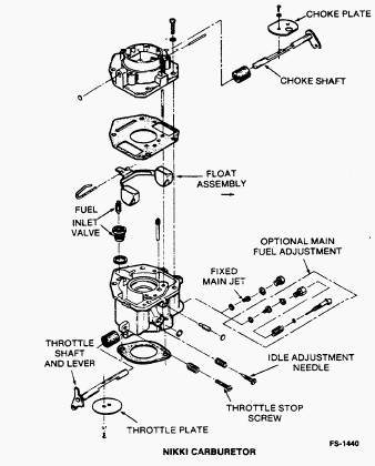
Disassembly (Nikki limited idle adjustment)
Remove main jet and idle adjustment needle. Remove attaching screws and
separate upper and lower carburetor sections. Carefully note position of
float assembly parts, then pull out retaining pin and float assembly.
Remove needle valve.
Cleaning and Repair
Soak all metal components not replaced in carburetor cleaner. Do not
soak non-metal floats or other non-metal parts. Follow the cleaning
manufacturer’s recommendations. Clean all carbon from the carburetor
bore, especially where the throttle and choke plates seat. Be careful
not to plug the idle or main fuel ports. Dry out all passages with low
pressure air (35 PSI). Avoid using wire or other objects for cleaning
which may increase the size of critical passages. Check the condition of
the adjustment needle; replace if damaged. Replace float if loaded with
fuel or damaged. Check the choke and throttle shafts for excessive play
in their bore. This condition may necessitate replacement of the
carburetor. Replace old components with new parts.
Reassembly and Installation (Nikki limited
idle adjustment)
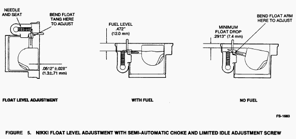
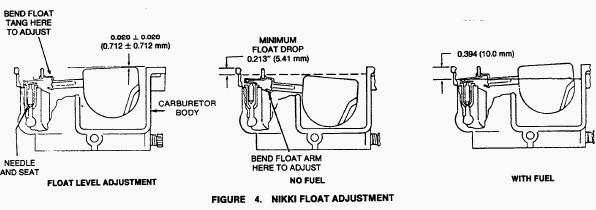
Install needle valve, main jet, and float assembly. Make sure float
pivot pin is properly placed and float moves freely without binding.
Turn carburetor on its side and measure float level. Adjust float level
only if necessary. Measure float drop (the distance from the top of
carburetor body to top of float). Adjust only if necessary.
Position gasket on lower carburetor section and install upper carburetor
section. Install idle adjustment screw, throttle stop screw, and fixed
main jet plug. Mount carburetor on intake manifold and install assembly
on engine. Mount air cleaner assembly. Connect air intake hose, breather
hose, fuel line, vacuum line, and throttle linkage. Adjust carburetor
and governor according to directions given in this section.
Onan B43G - Nikki Carburetor Adjustment
The carburetor idle and main mixture were set for maximum efficiency at
the factory and should normally not be disturbed. If adjustments seem
necessary, first be sure the ignition system is working properly and
governor sensitivity is properly adjusted. If adjustment is needed,
proceed as follows and refer to figures. Overtightening the mixture
adjustment screw will cause carburetor damage. Turn mixture adjustment
screw in only until light tension can be felt.
These initial adjustments will permit engine to start and warm up prior
to final adjustment.
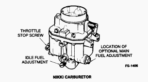
Nikki carburetor mixture screw settings - Turn idle mixture screw in
until lightly seated, then back idle mixture screw out 3/4 turn. On
engines equipped with main fuel adjustment, turn main mixture screw in
until lightly seated then back the main mixture screw out 1 -1 /4 to
1-1/2 turns.
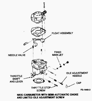
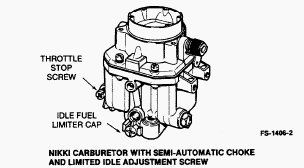
Nikki carburetor with semi-automatic choke and limited idle adjustment
screw - No initial mixture adjustments are required. When replacing idle
mixture screw, turn in until lightly seated, then turn screw back out
1-1 /4 turns. Replace limiter cap with the plastic stop approximately
centered.
Start the engine and allow it to warm up thoroughly (at least 10
minutes). Move the engine speed control to the slow position. Bend or
turn the low speed stop on the governor so the throttle stop screw on
the carburetor controls engine speed. Adjust throttle stop screw to
obtain the following rpm: Nikki carburetor 1000 rpm. Determine the best
idle mixture setting by first turning the idle adjustment screw in until
engine speed drops and then outward until engine speed drops again. Over
a narrow range between these two settings, engine speed remains at its
highest. Set the adjustment screw about 1 /8 turn outward (rich) from
the midpoint of this range.
Readjust throttle stop screw to obtain the RPM specified in step 3 and
release the governor arm. Adjust governor low speed stop for 1100 ± 100
rpm idle. Move the engine speed control to the fast position. Bend the
high speed stop on the governor so the engine runs at the equipment
manufacturer’s recommended speed. Check the main mixture adjustment
(optional on some carburetors) by rapidly accelerating the engine from
idle to full speed. The engine should accelerate evenly and without
hesitation. If it does not, turn the main adjustment screw out in 1 /8
turn increments until the engine accelerates smoothly, but do not turn
it out more than 1 /2 turn beyond the original setting.
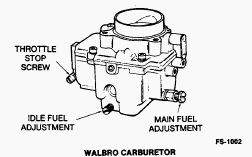
Marvel Schebler and Walbro Carburetor
Removal
Remove air cleaner and hose. Disconnect governor and throttle linkage,
choke control and fuel line from carburetor. Remove the four intake
manifold cap screws and lift complete manifold assembly from engine.
Remove carburetor from intake manifold.
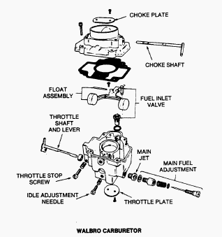
Disassembly
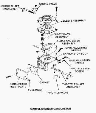
Remove throttle and choke plate retaining screws and plates. Pull out
throttle and choke shafts. Remove main adjustment and idle adjustment
needles. Remove attaching screws and separate upper and lower carburetor
sections. Carefully note position of float assembly parts, then pull out
retaining pin and float assembly. Remove needle and unscrew needle valve
seat.
Cleaning and Repair
Soak all metal components not replaced in carburetor cleaner. Do not
soak non-metal floats or other non-metal parts. Follow the cleaning
manufacturer’s recommendations. Clean all carbon from the carburetor
bore, especially where the throttle and choke plates seat. Be careful
not to plug the idle or main fuel ports. Dry out all passages with low
pressure air (35 PSI). Avoid using wire or other objects for cleaning
which may increase the size of critical passages. Check the condition of
the adjustment needle; replace if damaged. Replace float if loaded with
fuel or damaged. Check the choke and throttle shafts for excessive play
in their bore. This condition may necessitate replacement of the
carburetor. Replace old components with new parts.
Reassembly and Installation
Install needle valve and seat, main jet and float assembly. Make sure
that float pivot pin is properly placed and that float moves freely
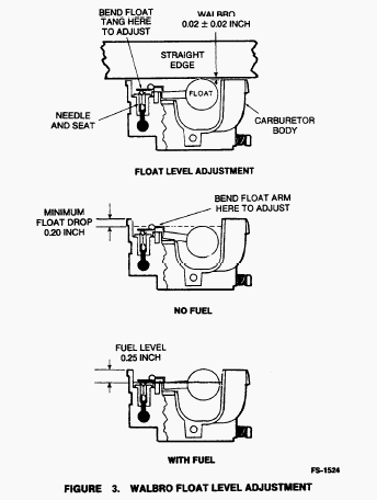
without binding. Gently push float tang down until needle just seats.
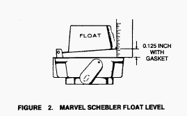
Measure float level. Adjust float level if necessary. Release float tang
and measure float drop. This is the distance from top of carburetor body
to top of float. When checking float level and float drop, measure to
float body, not seam. Position gasket on carburetor and attach
carburetor sections together with screws. Slide in throttle shaft and
install plate using new screws. Before tightening the screws, the plate
must be centered in the bore. To do so, back off the throttle stop screw
as necessary and completely close the throttle lever. Seat the plate by
tapping with a small screwdriver, then tighten screws. Install the choke
shaft and plate in the same manner.
Install idle adjustment screw, throttle stop screw, and fixed main jet
plug or optional main fuel adjustment needle. Mount carburetor on intake
manifold and install assembly on engine. Mount air cleaner assembly.
Connect air intake hose, breather hose, fuel line, vacuum line, and
throttle linkage. Adjust carburetor and governor according to directions
given in this section.
Onan B43G - Marvel Schebler and Walbro
Carburetor Adjustment
These initial adjustments will permit engine to start and warm up prior
to final adjustment.
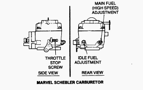
Marvel Schebler carburetor mixture screw settings - Turn both mixture
screws in until lightly seated, then back the idle mixture screw out 1
turn and the main mixture screw out 1-1 /4 turns.
Walbro carburetor mixture screw settings - Turn idle mixture screw in
until lightly seated, then back idle mixture screw out 1 -1 /8 turns. On
engines equipped with main fuel adjustment, turn main mixture screw in
until lightly seated then back the main mixture screw out 1-1/2 turns.
Start the engine and allow it to warm up thoroughly (at least 10
minutes). Move the engine speed control to the slow position. Bend or
turn the low speed stop on the governor so the throttle stop screw on
the carburetor controls engine speed. Adjust throttle stop screw to
obtain the following rpm: Marvel Schebler carburetor without governor
low speed adjustment screw 1200 rpm, with governor low speed adjustment
screw 1100 rpm. Walbro carburetor 1000 rpm. Determine the best idle
mixture setting by first turning the idle adjustment screw in until
engine speed drops and then outward until engine speed drops again. Over
a narrow range between these two settings, engine speed remains at its
highest. Set the adjustment screw about 1/8 turn outward (rich) from the
midpoint of this range.
Readjust throttle stop screw to obtain the RPM specified in step 3 and
release the governor arm. Adjust governor low speed stop for 1100 ± 100
rpm idle. Move the engine speed control to the fast position. Bend the
high speed stop on the governor so the engine runs at the equipment
manufacturer’s recommended speed. Check the main mixture adjustment
(optional on some carburetors) by rapidly accelerating the engine from
idle to full speed. The engine should accelerate evenly and without
hesitation. If it does not, turn the main adjustment screw out in 1 /8
turn increments until the engine accelerates smoothly, but do not turn
it out more than 1/2 turn beyond the original setting.
Onan B43G - Pulsating-Diaphragm Fuel Pump
Pulsating-diaphragm fuel pumps, or pulse pumps, rely on changes in
crankcase vacuum to create a pulsating movement of the pump diaphragm.
As the engine’s pistons move outward, a vacuum is created. This vacuum
is transmitted to the pump diaphragm, causing it to pull back and suck
fuel into the pump. As the engine’s pistons move inward, crankcase
vacuum is reduced and the diaphragm return spring pushes the pump
diaphragm forward, forcing fuel through the pump outlet. Before testing
make certain that fuel pump vacuum line connections are tight and free
of leaks.
Fuel Pump Test Procedure
Operate engine at an idle for five minutes to ensure that carburetor is
full of fuel. Shut engine off and remove fuel inlet line from fuel pump.
Connect a vacuum gauge to fuel pump inlet using a piece of fuel hose
with clamps. Start engine and allow to idle for at least five seconds.
Record vacuum gauge reading. Move throttle control to high idle
position. Wait at least five seconds and record vacuum gauge reading.
Shut engine off and remove vacuum gauge hose from fuel pump inlet.
Connect fuel inlet line to fuel pump. Remove fuel outlet line from fuel
pump. Connect a pressure gauge to fuel pump outlet using a piece of fuel
hose with clamps. Start engine and allow to idle for at least five
seconds. While holding pressure gauge level with pump outlet record
pressure gauge reading. Move throttle control to high idle position and
allow engine to run for at least five seconds. While holding pressure
gauge level with pump outlet record pressure gauge reading.
Onan B43G - Air Cleaner
Dirty air cleaner element can cause engine damage. Ensure air cleaner
clean and free of excess debris. Engine is equipped with a paper
element. If the engine is equipped with polyurethane precleaner, it must
be removed, cleaned and oiled every 25 hours of operation; more often
under extremely dusty conditions. To clean precleaner, wash in water and
detergent. Remove excess water by squeezing like a sponge and allow to
dry thoroughly. Distribute two tablespoons of SAE-30 engine oil evenly
around the precleaner. Knead into the precleaner to dis¬tribute oil
evenly. Wring out excess oil. Depending on conditions in which the
engine is operating, the inner paper element should be replaced whenever
it becomes excessively dirty or oily. Running engine without air cleaner
element will result in engine damage. Do not run engine without air
cleaner element installed.
________________________________________________________________________________
________________________________________________________________________________________
| KOHLER ENGINES SPECS AND SERVICE DATA |
 CH12.5
 CH14S
CH14S CH15S
CH15S CH16
CH16 CH18S
CH18S________________________________________________________________________________________
 CH23S
CH23S CH25S
CH25S CH640S
 CH730S
 CH750S
________________________________________________________________________________________
________________________________________________________________________________________
 CV15S
CV15S CV16S
CV16S CV18S
CV18S CV20S
CV20S CV22S
CV22S________________________________________________________________________________________
 CV23S
CV23S CV25S
CV25S CV490S
 CV491S
 CV730S
________________________________________________________________________________________
 CV740S
 K161
K161 K181
K181 K241
K241 K301
K301________________________________________________________________________________________
 K321
K321 K341
K341 K361
K361 M18
M18 M20
M20________________________________________________________________________________________
 SV470S
 SV530S
 SV540S
 SV590S
 SV600S
________________________________________________________________________________________
 SV710
SV710 SV715
SV715 SV725S
 SV730S
 SV735
SV735________________________________________________________________________________________
| KAWASAKI ENGINES SPECS AND SERVICE DATA |
 FA210
FA210 FA210D
 FB460V
 FC150V
 FC290V
________________________________________________________________________________________
 FC420V
 FC540V
 FD501V
 FD590V
 FD620D
________________________________________________________________________________________
 FD731V
 FD750D
 FH430V
 FH500V
 FH531V
________________________________________________________________________________________
 FH580V
 FH601V
 FH680V
 FS541V
 FS600V
________________________________________________________________________________________
 FS651V
 FX651V
 FX691V
 FX730V
________________________________________________________________________________________
 FH541V
 FH641V
 FH661V
 FH721V
 FS730V
________________________________________________________________________________________
| BRIGGS AND STRATTON ENGINES SPECIFICATIONS |
 252707
 253707
 282707
 286707
 303777
________________________________________________________________________________________
 28N707
 28M707
 28Q777
 28R707
 28S777
________________________________________________________________________________________
 311707
 31A607
 31C707
 31N707
 31Q777
________________________________________________________________________________________
 31R977
 31R777
 31P777
 31P977
 350777
________________________________________________________________________________________
 402707
 422707
 42A707
 331777
 331877
________________________________________________________________________________________
| HONDA ENGINES SPECS AND SERVICE DATA |
 G50
G50 G100
G100 GC135
GC135 GC160
GC160 GC190
GC190________________________________________________________________________________________
 GS190
GS190 GX100
GX100 GX120
GX120 GX160
GX160 GX200
GX200________________________________________________________________________________________
 GXV120
 GXV160
 GXV270
 GXV340
 GXV390
________________________________________________________________________________________
 GXV610
 GCV520
 GCV530
 GXV620
 GXV630
________________________________________________________________________________________
 GCV145
 GCV160
 GCV170
 GCV190
 GCV200
________________________________________________________________________________________
 GSV190
 GX110
GX110 GX140
GX140 GV100
GV100 GXV140
________________________________________________________________________________________