________________________________________________________________________________
Tractor Clutch actuator
The tractor clutch actuator is intended for controlling the clutch in
both forward and reverse motion of the tractor.
The clutch actuator is of hydrostatic type with overhang pedals and
hydraulic booster.

1 – reservoir; 2 – spring; 3, 17 – bolt; 4, 8, 14, 18, 27, 42 – nut; 5,
15, 43 – fork; 6, 16, 34, 44 – pin; 7 –clutch pedal for forward motion;
9, 12, 31, 32 – piston lifter; 10 – clutch master cylinder for forward
motion; 11 – oil pipeline; 13 – boot; 19 – master cylinder for reverse;
20 – clutch pedal for reverse; 21, 25 – tubing; 22 – tap; 23 – piston;
24 – flexible hose; 26 – support; 28 – protective cap; 29 – overflow
valve; 30 – clutch master cylinder; 33, 40 – bracket; 35 – cotter pin;
36 – washer; 37 – cover; 38 – piston; 39 – hydraulic booster; 41 – rod;
45 – lever; 46 – hose; 47 – release spring.
The actuator consists of the clutch master cylinders (10) (for forward
motion) and (19) (in the reverse mode), overhang pedals (7) (for forward
motion) and (20) (in the reverse mode), tap (22) (for automatic
switching from the forward motion to the reverse mode or vice versa),
service cylinder (30), hydraulic booster (39), lever (45), reservoir
(1), connecting tubing and oil pipes.
The flow-type hydraulic booster (39) is intended for reducing the force
to be applied to the pedals (7) and (20) for disengaging the tractor
clutch.
It is connected with the oil discharge flow of the metering pump via oil
pipe (11), and with the drain into the reservoir via hose (46).
On stepping on the pedal (7) in the forward motion mode, the brake fluid
is passed from the clutch master cylinder (10) through the tubing (25)
to the tap (22).
In the tap (22), the piston moves to the rightmost position and closes
the input of the tubing (21).
Then the brake fluid is passed through the flexible hose (24) to the
clutch slave cylinder (30) while moving the piston lifter (31).
The piston lifter (31) acts upon the piston lifter (32) of the hydraulic
booster (39) that causes the operation of the hydraulic booster and
advancement of the piston and rod (41) rotating the lever (45) connected
with the clutch release shifter that in turn causes the disengagement
between the engine and the transmission.
On stepping on the pedal (2) in the reverse mode, the brake fluid is
passed from the clutch master cylinder (19) through the tubing (21) to
the tap (22). In the tap (22), the piston moves to the leftmost position
and closes the inlet of the tubing (25).
Then the brake fluid is passed through the flexible hose (24) to the
working cylinder (30) and acts as described above.
________________________________________________________________________________
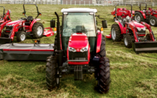 SPECS
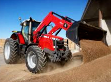 LOADERS
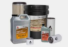 MAINTENANCE
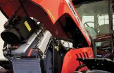 PROBLEMS
________________________________________________________________________________________
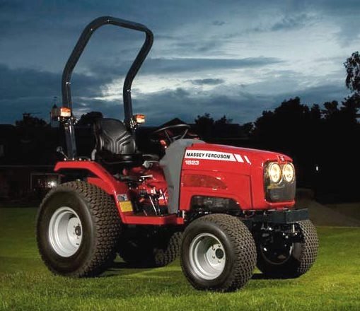 MF 1523
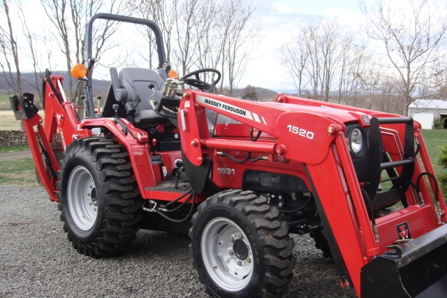 MF 1531
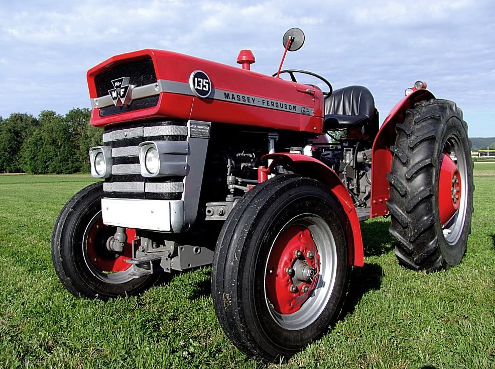 MF 135
 MF 1547
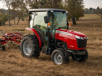 MF 1635
________________________________________________________________________________________
 231
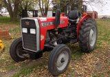 231S
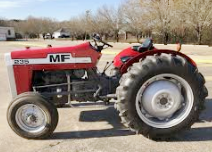 235
 240
 241
________________________________________________________________________________________
_______________________________________________________________________________________
 255
 265
 274
 285
 375
________________________________________________________________________________________
________________________________________________________________________________________
 916X Loader
 921X Loader
 926X Loader
 931X Loader
 936X Loader
________________________________________________________________________________________
 941X Loader
 946X Loader
 951X Loader
 956X Loader
 988 Loader
________________________________________________________________________________________
 1655
 GS1705
 1742
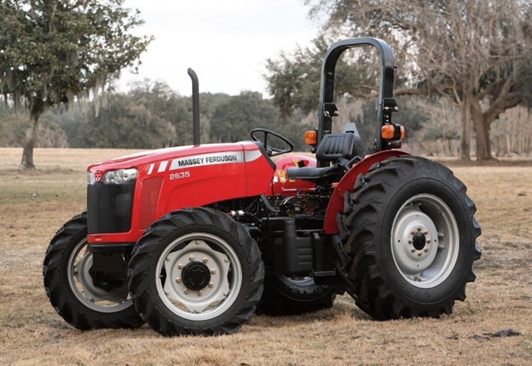 2635
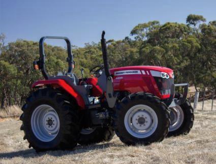 4608
________________________________________________________________________________________
 1080
 1100
 2615
 3050
 3060
________________________________________________________________________________________
 4708
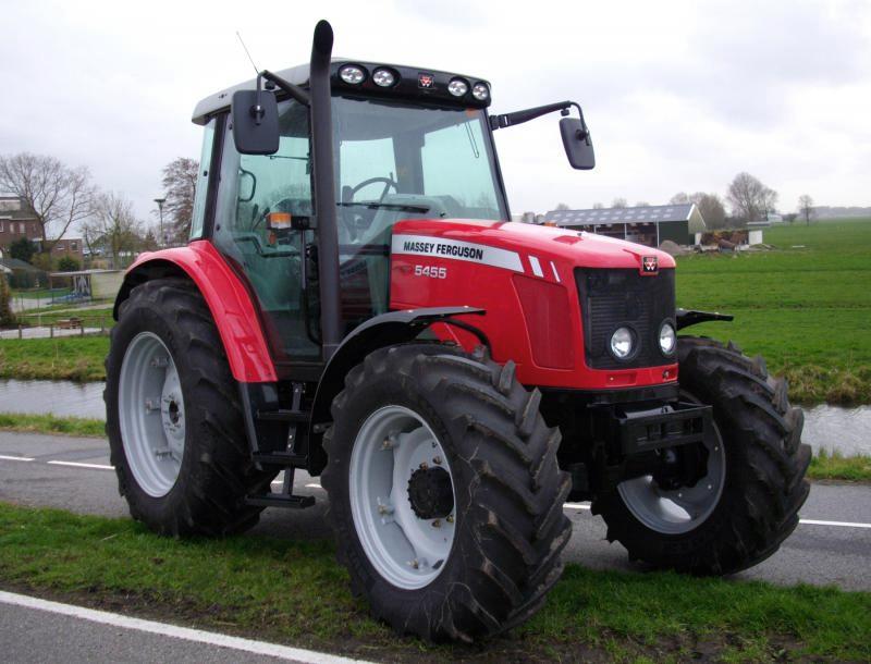 5455
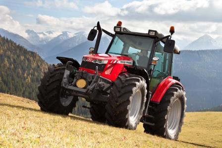 5450
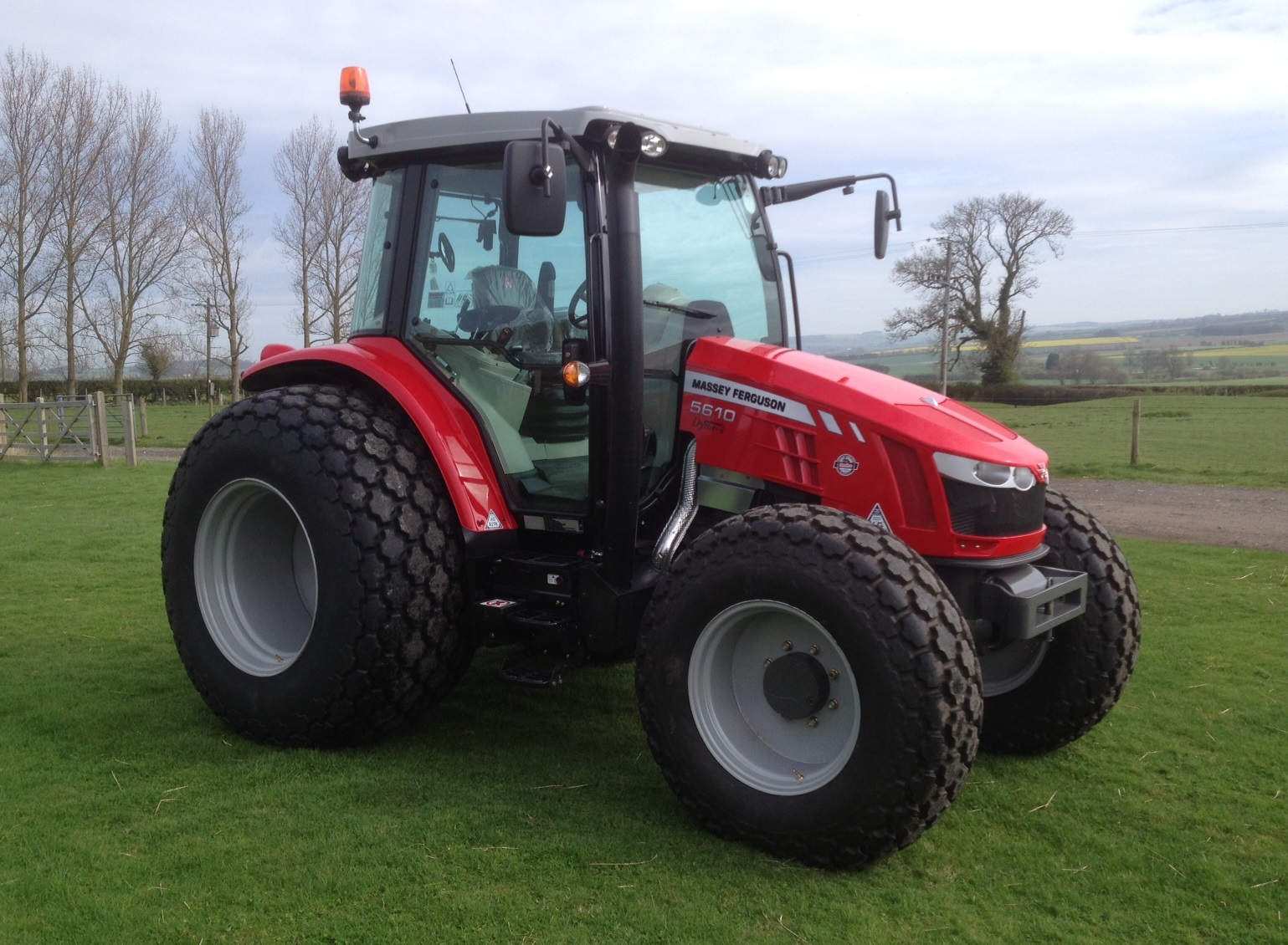 5610
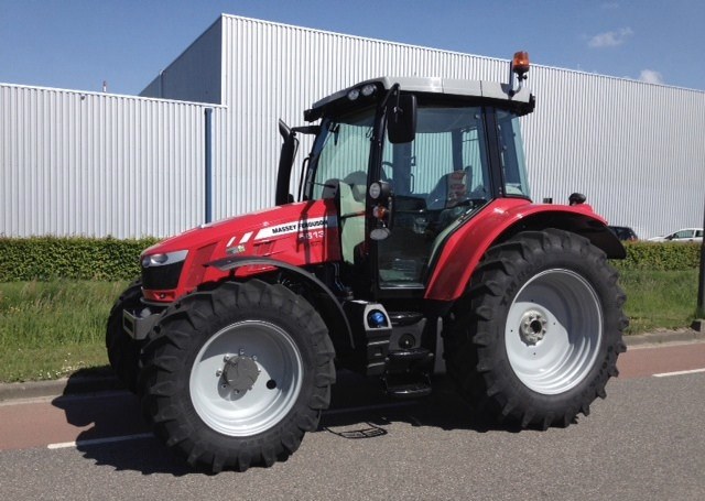 5613
________________________________________________________________________________________
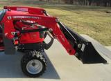 DL95 Loader
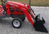 DL100 Loader
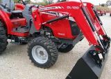 DL120 Loader
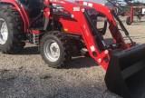 DL125 Loader
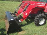 DL130 Loader
________________________________________________________________________________________
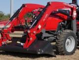 DL135 Loader
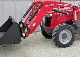 DL250 Loader
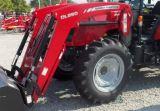 DL260 Loader
 L90 Loader
 L100 Loader
________________________________________________________________________________________
 6499
 7480
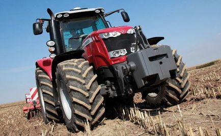 7618
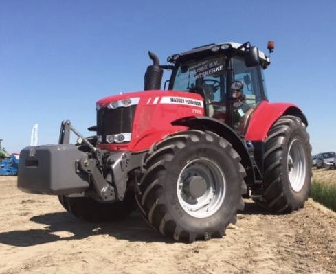 7726
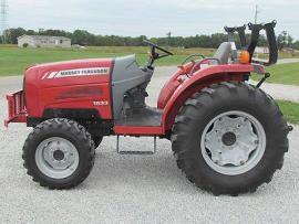 1533
________________________________________________________________________________________
 2604H
 2607H
 4455
 4610M
 4710
________________________________________________________________________________________
 L105E Loader
 L210 Loader
 1014 Loader
 1016 Loader
 1462 Loader
________________________________________________________________________________________
 1525 Loader
 1530 Loader
 232 Loader
 838 Loader
 848 Loader
________________________________________________________________________________________
 5712SL
 6713
 6715S
 7475
 7615
________________________________________________________________________________________
 7716
 7724
 8240
 8650
 8732
________________________________________________________________________________________
 246 Loader
 1036 Loader
 1038 Loader
 1080 Loader
 856 Loader