________________________________________________________________________________
Kubota BX23, BX23S, BX24, BX25, BX25D hydraulic system - Adjusting and servicing
Kubota BX23, BX23S, BX24, BX25, BX25D - Mower linkage
The mower rear link and the lift arm are linked with the mower lift arm,
the lift upper boss and the lift lower boss. As the hydraulic control
lever moves to lift position, lift arm is raised and the lift bracket is
pulled to pull the lift links to the rearward. As a result, mower rear
link is lifted. The cutting height adjusting dial adjusts cutting height
of mower by rotating the adjusting cam. The position of mower rear link
is adjusted by changing the length of the adjusting bolt.
Adjusting mower lift linkage
Check the lift arm free play. Loosen the adjusting nut and start the engine. Move the hydraulic control lever to Lift position until the relief valve operating (Uppermost position). Adjusting bolt until the clearance between stopper and mower rear link L.H. Clearance (Kubota BX23, BX23S, BX24, BX25, BX25D) - 0 to 0.5 mm / 0 to 0.01 in. Secure the lock nut.
Disassembling mower linkage
Remove
the clevis pin and remove the lift link rear L.H. Remove the pin and
remove the mower rear links. Remove both side of boss and remove the
lift link rear R.H. Remove the cutting height adjusting dial knob.
Remove the nut and remove the adjusting cam and cutting height adjusting
rod. Removing mower linkage and wire harness - Disconnect the mower
linkage. Remove the wire harness clamp and wire harness from the
hydraulic cylinder block.
Kubota BX23, BX23S, BX25, BX25D - Hydraulic cylinder
Checking hydraulic cylinder bore
Check the cylinder internal surface for scoring or damage. Measure the cylinder I.D. with a cylinder gauge. If the measurement exceeds the allowable limit, replace the hydraulic cylinder block. Cylinder I.D - 80.05 to 80.15 mm / 3.152 to 3.155 in. Checking hydraulic arm shaft bushing - Hydraulic arm shaft O.D. L.H - 31.925 to 31.950 mm / 1.2569 to 1.2578 in. R.H - 29.925 to 29.950 mm / 1.1782 to 1.1791 in. Visually inspect the DX bushings for signs of wear or damage. The DX bushing tends to show concentrated wear. If the DX bushing is worn beyond the alloy thickness, replace it. Hydraulic arm shaft bushing Alloy thickness - 0.57 mm / 0.022 in.
Removing hydraulic cylinder block
Remove the hydraulic hose. Remove the hydraulic
cylinder block mounting bolts. Remove the hydraulic cylinder block.
Hydraulic cylinder block mounting bolt - 40 to 44 Nm / 29 to 32 lbf-ft.
Removing lift rod and lower link - Remove the top lin. Remove the
stopper pin and remove the check chain plate. Move the bushes to inside.
Move the shaft to right side and remove the lower link as a unit.
Removing hydraulic piston - Inject the compressed air into the hydraulic
cylinder, and remove the hydraulic piston. Apply transmission fluid to
the O-ring. Replace the O-ring if it is damaged, worn or scratched,
which may cause oil leakage. Removing lowering speed adjusting valve -
Remove the internal snap ring and remove the lowering speed adjusting
shaft. Remove the ball and spring.
Kubota BX23, BX23S, BX24, BX25, BX25D - Hydraulic pump
Checking hydraulic pump oil flow
Disconnect the power steering controller hose (inlet) from the power steering pipe. Cap the power steering pipe with plug. Remove the hydraulic pipe behind the hydraulic cylinder and fix the flow meter hose and the flow (meter) inlet. Remove the transmission fluid filling plug, then fix the flow meter hose and the flowmeter (outlet). If the flow volume is insufficient, replace the pump. Pump oil flow (Hydraulic pumpdelivery at no pressure) - 24.9 L/min. After measuring the flow volume, remove the flow meter then reassembling the hydraulic pipe to the original position.
Removing lift rod and lower link
Remove the top link. Remove the stopper pin and remove the check chain plate. Move the bushes to inside. Move the shaft to right side and remove the lower link as a unit. Removing hydraulic pump - Disconnect the mower linkage. Remove the lift arm L.H. Remove the hydraulic pipes. Remove the hydraulic pump. Since the mounting bolt is installed through the transaxle case to the transmission oil tank, seal the sealing tape to the mounting bolt securely. Hydraulic pump mounting bolt (M6) - 7.9 to 9.3 Nm / 5.8 to 6.8 lbf-ft. Hydraulic pump mounting bolt (M8) - 18 to 20 Nm / 13 to 15 lbf-ft.
Checking clearance between tip of gear tooth and casing
Measure the gear O.D. with an outside micrometer. Gear O.D (Kubota BX23, BX23S, BX24, BX25, BX25D) - 33.520 to 33.530 mm / 1.3197 to 1.3200 in. Measure the casing I.D. with a cylinder gauge and calculate the clearance. Case I.D - 33.570 to 33.577 mm / 1.3217 to 1.3219 in. If the clearance exceeds the allowable limit, replace the assembly. Clearance between tip of gear tooth and casing - Allowable limit 0.15 mm / 0.0059 in.
Checking clearance between bushing and shaft
Measure the gear shaft O.D. with an outside micrometer.
Shaft O.D - 14.970 to 14.980 mm / 0.58937 to 0.58976 in. Measure the
bushing I.D. with a cylinder gauge and calculate the clearance. Bushing
I.D - 15.000 to 15.061 mm / 0.59056 to 0.59295 in. If the clearance
exceeds the allowable limit, replace it. Clearance between bushing and
shaft - 0.020 to 0.091 mm / 0.00079 to 0.0035 n. Checking side plate
thickness - Measure the side plate thickness with an outside micrometer.
If the thickness is less than the allowable limit, replace it. Side
plate thickness - 2.48 to 2.50 mm / 0.0977 to 0.0984 in.
Kubota BX23, BX23S, BX24, BX25, BX25D - Control valve
Removing control valve
Remove the control valve. Remove the internal snap ring and draw out the spool. Removing control valve lever - Pull out the pin. Remove the control valve lever and arm. Removing lift arm, hydraulic arm shaft and hydraulic arm - Remove the external snap rings and remove the lift arms. Draw out the hydraulic arm shaft. Align the alignment marks of the hydraulic arm and hydraulic arm shaft. Align the alignment marks of the lift arms and hydraulic arm shaft. Apply grease to the right and left bushings and O-rings. Removing control valve (Front loader) - Disconnect the hydraulic hoses. Disconnect hydraulic pipes. Disconnect the rods. Remove the control valve from the valve stay. After reassembling a valve, check for oil leakage by starting up engine.
Disassembling front loader control valve
Remove the load check valve assemblies. Remove the detent plug assemblyand plug. Remove the bucket spool with parts from the valve body. Remove the boom spool with parts from the valve body. Clean all parts with a suitable solvent, and dry with a lint-free cloth or air. Visually inspect all parts for damage. When installing the spools into the valve body, be careful not to damage the O-rings.
Checking relief valve setting pressure
Disconnect the hydraulic hose from the right side of the transaxle. Install the hydraulic hose and adaptor with pressure gaug. Start the Kubota BX23, BX23S, BX24, BX25, BX25D engine and set at maximum speed. Engine speed / Oil temperature Maximum 45 to 55C / 113 to 131F. Move the control lever all way up to operate the relief valve and read the gauge. If the pressure is not within the factory specifications, adjust with the adjusting shim. Relief valve setting pressure - 12.3 to 12.7 MPa / 1780 to 1840 psi. Thickness of shim - 0.1 mm / 0.004 in. 0.2 mm / 0.008 in. 0.4 mm / 0.02 in. 0.269 MPa (39.0 psi) pressure is increased whenever the thickness of adjusting shim is increased by 0.1 mm (0.004 in.).
Function of loader control valveThe control valve assembly consists of one casting block and four major sections. The boom control valve is of 4-position, 6-connection, detent, spring center type, consisting of a mono block valve housing, spool, load check valve, etc. This valve has A1 and B1 ports and controls oil flow to the boom cylinder. The bucket control valve is of 3-position, 6-connection, no detent, spring center type, consisting of a mono block valve housing, spool, load check valve, etc. This valve has A2 and B2 ports and controls oil flow to the bucket cylinder. The P port is connected to the outlet port of hydraulic block by the hydraulic pipe. The T port is connected to the tank port of hydraulic block by the hydraulic pipe. Power beyond (PB port) - This section has PB port which is connected to the inlet port of hydraulic block by the hydraulic hose, and feeds oil to the three point hydraulic control valve.
Loader control lever in neutral position - When the
loader control lever is set at neutral position, the hydraulic oil
enters from P port (P), flows through the boom spool valve and the
bucket spool valve, and exits at PB port (PB).
Loader control lever in up position - When the loader
control lever is set at up position, the boom spool valve moves outward.
This creates an oil passage between the boom spool valve and the front
loader control valve. The pressured oil from the pump port (P) enters to
this oil passage. The pressured oil is delivered to the boom cylinder
through 1B port (1B). This extends and raises the boom cylinder. When
the boom spool valve moves outward, a passage between the boom spool
valve and 1A port (1A) is created. The return oil from the boom cylinder
enters 1A port (1A), flows through the bucket spool valve and exits to
PB port (PB).
Loader control lever in down position - When the loader
control lever is set at down position, the boom spool valve moves
inward. This creates an oil passage between the boom spool valve and the
front loader control valve. The pressured oil from the pump port (P)
enters to the newly opened passage. The pressured oil is delivered to
the boom cylinder through 1A port (1A). This retracts and lowers the
boom cylinder. When the boom spool valve moves inward, a passage between
the boom spool valve and 1B port (1B) is created. The return oil in the
boom cylinder enters 1B port (1B), flows to the bucket spool valve, and
exits to the PB port (PB).
Loader control lever in floating position (Kubota BX23,
BX23S, BX24, BX25, BX25D) - When the loader control lever is set to
floating position, the boom spool valve moves further inward. This
creates oil passages at 1A port (1A) and 1B port (1B), as well as a
passage between the boom spool valve and the front loader control valve.
The low pressured oil from the pump port (P) flows through the bucket
spool valve, and exits to the PB port. The low pressured return oil in
the boom cylinder enters 1A port (1A), flows through the boom spool
valve, andgoes to the tank port (T). The other low pressured return oil
in the boom cylinder enters 1B port (1B), flows through the boom spool
valve, and goes to the tank port (T). As a result, the boom is floating.
Loader control lever in roll-back position - When the
loader control lever is set at roll-back position, the bucket spool
valve moves outward. This creates oil passages at 2A port (2A) and 2B
port (2B). The pressured oil from the pump port (P) flows through 2B
port (2B) to the bucket cylinder. The low pressured return oil from the
bucket cylinder enters 2A port (2A), flows through the front loader
control valve, and goes to the tank port (T). As a result, the bucket
moves to roll-back position.
Loader control lever in dump position - When the loader
control lever is set to the dump position, the bucket spool valve moves
to the right. This creates an oil passage at 2A port (2A). The passage
between 2B port (2B) and T port (T) is also opened. The pressure-fed oil
from P port (P) flows to the neutral passage through the boom control
section. As the passage to the PB port (PB) is closed by the bucket
spool valve, the arriving oil opens the load check valve and flows to 2A
port (2A) through the notched section of the bucket spool valve. This
extends the bucket cylinder. Return oil from the bucket cylinder enters
2B port (2B) and travels throughout the valve to go to the transmission
case through T port (T).
- Kubota BX23, BX23S, BX24, BX25, BX25D Transaxle adjusting
- Kubota BX23, BX23S, BX24, BX25, BX25D Transaxle service
- Kubota BX23, BX23S, BX24, BX25, BX25D hydrostatic transmission
- Kubota BX23, BX23S, BX24, BX25, BX25D Front axle
- Kubota BX23, BX23S, BX24, BX25, BX25D Steering
- Kubota BX23, BX23S, BX24, BX25, BX25D electrical system
________________________________________________________________________________
________________________________________________________________________________________
________________________________________________________________________________________
________________________________________________________________________________________
________________________________________________________________________________________
________________________________________________________________________________________
________________________________________________________________________________________
________________________________________________________________________________________
________________________________________________________________________________________
________________________________________________________________________________________
________________________________________________________________________________________
________________________________________________________________________________________
________________________________________________________________________________________
________________________________________________________________________________________
________________________________________________________________________________________
________________________________________________________________________________________
________________________________________________________________________________________
________________________________________________________________________________________
________________________________________________________________________________________
________________________________________________________________________________________
________________________________________________________________________________________
________________________________________________________________________________________
________________________________________________________________________________________
________________________________________________________________________________________
________________________________________________________________________________________
________________________________________________________________________________________
________________________________________________________________________________________
________________________________________________________________________________________
________________________________________________________________________________________

 SPECIFICATIONS
 LOADERS
 ENGINES
 INSTRUCTIONS
 PROBLEMS
 B2320
B2320 B2630
B2630 B2920
B2920 B3300SU
 BX2360
 L245
L245 L260
L260 L275
L275 L285
L285 L305
L305 D662
D662 D722
D722 D750
D750 D782
D782 D850
D850 LA302
LA302 LA304
LA304 LA340
LA340 LA344
LA344 LA351
LA351 BX2660
 L2501
L2501 L3240
L3240 L3540
L3540 L3940
L3940 D902
D902 D905
D905 D950
D950 D1005
D1005 D1100
D1100 B1630
B1630 BF400
BF400 BF400G
 LA181
LA181 LA203
LA203 LA211
LA211 LA243
LA243 LA271
LA271 LA272
LA272 LA301
LA301 L175
L175 L185
L185 L210
L210 L225
L225 L235
L235 D1105
D1105 D1503
D1503 D1703
D1703 D1803
D1803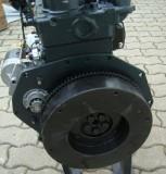 V1200
V1200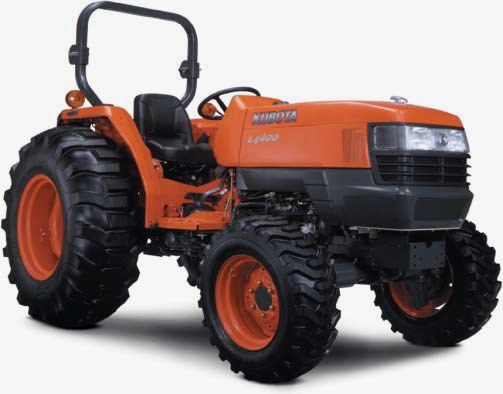 L4400
L4400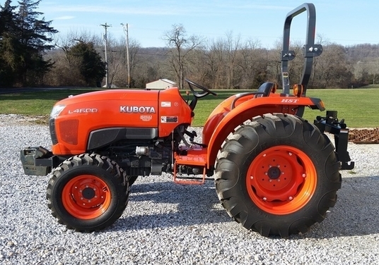 L4600
L4600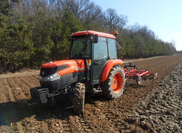 L5040
L5040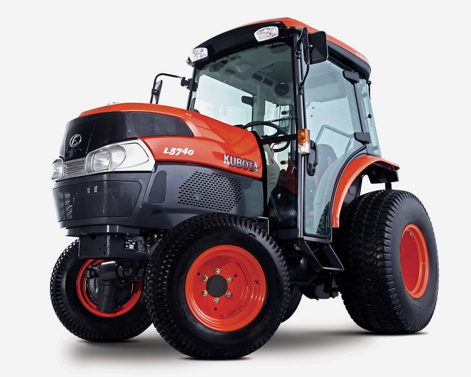 L5740
L5740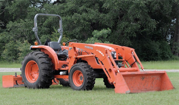 MX4700
 LA352
LA352 LA364
LA364 LA401
LA401 LA402
LA402 LA434
LA434 LA463
LA463 LA481
LA481 LA482
LA482 LA504
LA504 V1205
V1205 V1305
V1305 V1505
V1505 V2203
V2203 V2403
V2403 B2710
B2710 BX23S
BX23S B3350
B3350 BX1880
 L4701
L4701 LA513
LA513 LA514
LA514 LA524
LA524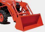 LA525
LA525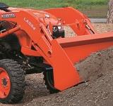 LA534
LA534 LA555
LA555 LA680
LA680 LA681
LA681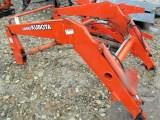 LA682
LA682 LA703
LA703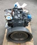 Z482
Z482 Z602
Z602 Z750
Z750 Z1100
Z1100 Z1300
Z1300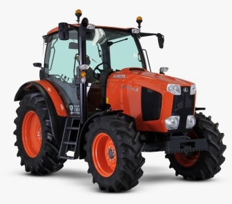 M100GX
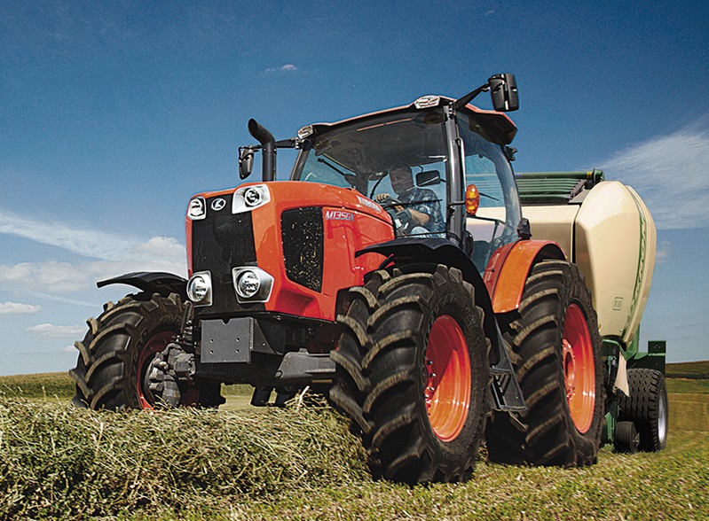 M135GX
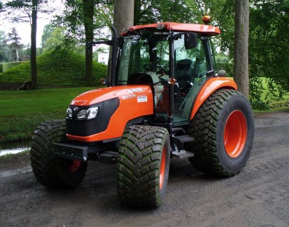 M6040
M6040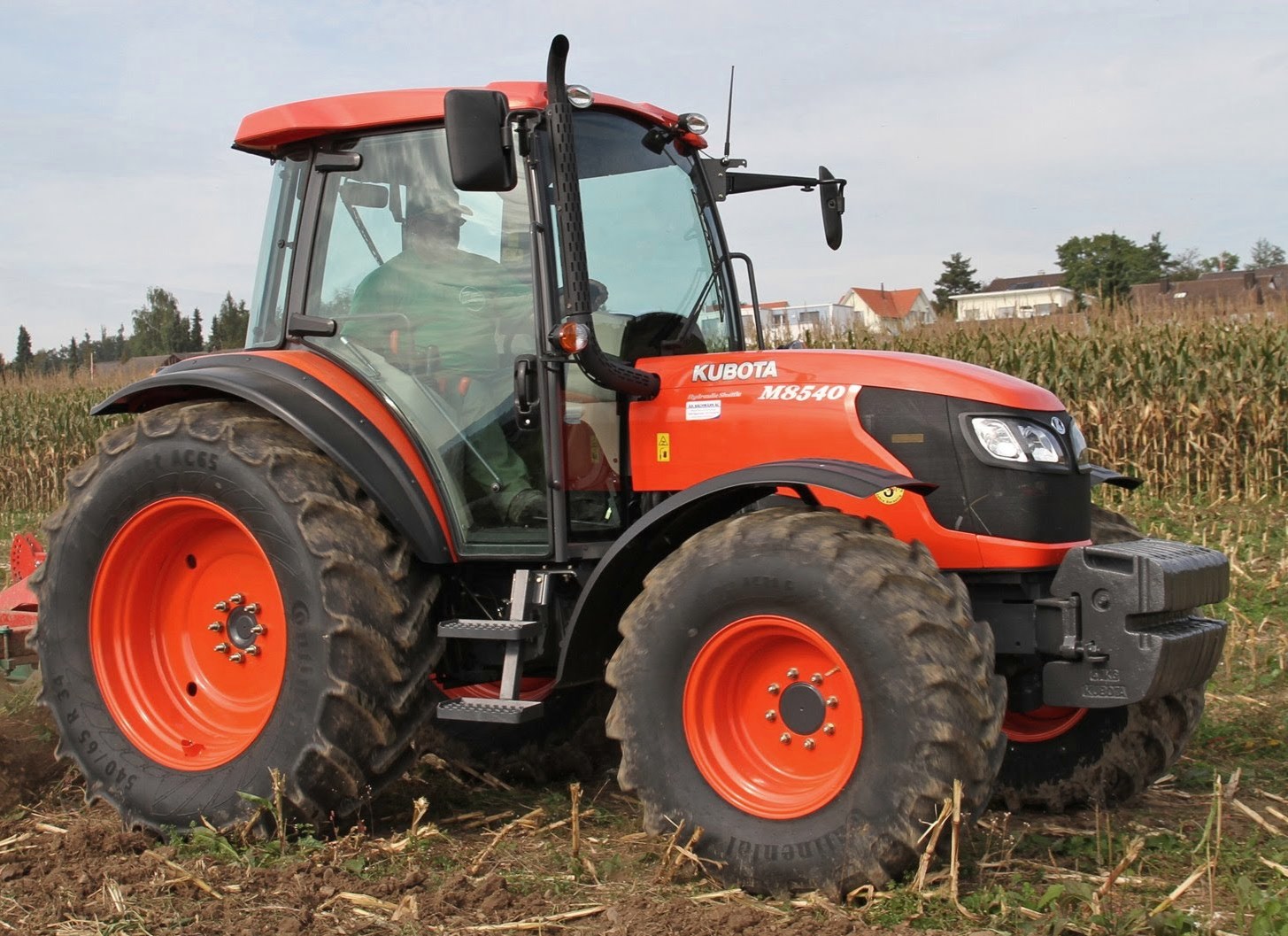 M8540
M8540 M95X
M95X LA714
LA714 LA723
LA723 LA724
LA724 LA764
LA764 LA765
LA765 LA805
LA805 LA844
LA844 LA852
LA852 LA853
LA853 LA854
LA854 M5-091
 BX2680
 MX5200
 BX2380
 L3901
L3901 LA1002
 LA1055
 LA1065
 LA1153
 LA1154
 LA1251
 LA1301S
 LA1353
 LA1403
 LA1601S
 LA1854
 LA1944
 LA1953
 LA2253
 LM2605