________________________________________________________________________________
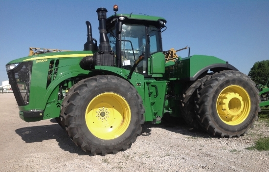
John Deere 2305 Attachments
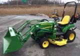
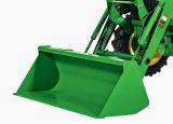
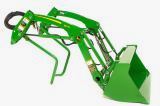
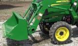
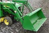
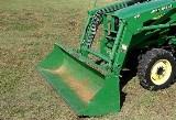
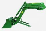
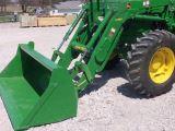
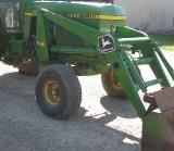
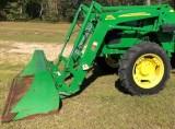
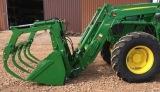
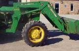
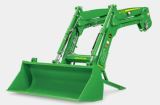
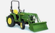
John Deere 2305 Front End Loader
200X Loader Specifications
Type of Attachment - Front End Loader
Compatibility - JD 2305
Lift capacity at pivot pin (max. ht.) - 562 lb. (255 kg)
Lift capacity at 500 mm ahead of pivot pin - 395 lb. (179 kg)
Lift capacity to 59 in. at pivot pin - 708 lb. (321 kg)
Lift capacity to 59 in. at 500 mm ahead - 516 lb. (234 kg)
Max. lift height at pivot pin - 73.4 in. (1865 mm)
Reach at max. height - 32.5 in. (826 mm)
Breakout force at pivot pin - 1,693 lbf. (7310 N)
Dump angle - 39 deg.
Rollback angle - 31 deg.
Loader raising/lowering time - 5.56/3.39 sec.
Bucket dump time/regen - 5.56/2.17 sec.
Bucket rollback time - 3.39 sec.
Attach 200X Loader to John Deere
2305 Tractor - Remove retaining ring and pin from each
loader mast. Start JD 2305 tractor engine. Drive tractor slowly under
200X loader, close enough to connect hydraulic hoses. Engage tractor
parking brake and/or place transmission in PARK. Shut off tractor engine
and remove key. Route hoses through hose support on inside of right-hand
loader mast. Connect hydraulic hoses to couplers on tractor using
color-coded caps on hoses to match numbers and/or colors on decal by
coupler plate. Start tractor engine.
Extend 200X loader lift cylinders. Drive tractor slowly, straight into
loader so loader masts line up with mounting frames. Slowly retract lift
cylinders fully. Notch will catch on bushing, positioning masts onto
mounting frames. Dump bucket 10-20 deg. so front wheels come off ground
slightly. Make sure bushing is installed in inner mast hole before
installing pin and retaining ring. Install pin in hole and fasten with
retaining ring. Remove lifting straps and overhead hoist. Extend lift
cylinders and lift bucket from ground to ensure loader is properly
mounted.
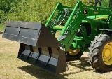
200CX Loader Specifications
Type of Attachment - Front End Loader
Model - 200CX Loader
Compatibility - John Deere 2305
Height (to pin) - 89,5 in. (2,27 m)
Clearance, dumped bucket - 58,5 in. (1,48 m)
Dump reach - 29,5 in. (0,74 m)
Dump angle - 38 deg.
Reach at ground - 50,3 in. (1,27 m)
Rollback angle at ground - 25 deg.
Rollback angle, raised - 105 deg.
Breakout force (at pin) - 2,239 lbs (1015 kg)
Breakout force (at 0,5 m) - 1,515 lbs (687 kg)
Breakout force (bucket) - 1,702 lbs (772 kg)
Lift to full height (at pin) - 902 lbs (409 kg)
Lift to full height (at 0,5 m) - 629 lbs (285 kg)
Lift to 1.5m (at pin) - 1,124 lbs (509 kg)
Lift to 1.5m (at 0,5 m) - 827 lbs (375 kg)
Bucket width - 53 in. (1,34 m)
Raise time to height - 3,19 sec
Bucket dump time - 3,19 sec
Lowering time - 1,95 sec
Rollback time - 1,95 sec
John Deere 2305 Backhoe
260 Backhoe Specifications
Type of Attachment - Backhoe
Compatibility - John Deere 2305
Max. Digging Depth - 80 in. (2020 mm)
Digging Depth 2 ft - 74.5 in. (1880 mm)
Swing Arc - 150 deg.
Angle of departure - 20 deg.
Loading Height - 60 in. (1500 mm)
Reach from Swing Pivot - 104 in. (2620 mm)
Transport Height - 66 in. (1670 mm)
Bucket Rotation - 180 deg.
Loading Reach - 33 in. (830 mm)
Stabilizer Spread, Up - 47 in. (1185 mm)
Stabilizer Spread, Down - 74 in. (1870 mm)
Bucket Force - 2036 lb. (9056 N)
Dipper Force - 1187 lb. (5280 N)
Shipping Weight - 750 lb. (330 kg)
Buckets - 8 in, 12 in, 16 in.
Mid-Mower Compatible - Yes
Swing Cylinder - Single
Attach John Deere 260 backhoe
- Back up tractor to within 20 cm (8 in.) from backhoe. Park JD 2305
tractor. Connect power beyond system. Remove backhoe boom-lock pin. Back
tractor closer to backhoe and use backhoe control levers to align
backhoe frame with backhoe mounts on tractor. Use stabilizer controls to
raise and lower stabilizers as needed to position notches in backhoe
frame above mount hooks. Use stabilizers to lower hooks on notches on
the back of tractor. Use boom control to raise boom into back of tractor
and install pins to secure backhoe to tractor. Use pins to secure
backhoe to tractor. Machine is now ready for use.
Detach 260 backhoe -
Lower stabilizers to a few inches from the ground. Center boom and
install swing-locking pin. Remove boom-locking pin if installed. Extend
dipper stick and lower boom. Rotate bucket until top edge is parallel
with ground. Use boom control lever to lower and place slight down
pressure on backhoe. Remove pins from backhoe mounts. Use backhoe
controls to lower backhoe toward the ground. Use stabilizer controls to
lift backhoe off lower mounting notches. Lower backhoe to ground.
Disconnect hydraulic hoses and close connection on the tractor and
backhoe side. Drive away for tractor use.
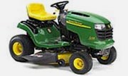
John Deere 2305 Mower Deck
261 Mower Specifications
Mower Type - Rear-Mounted
Cutting Width - 60 in. (1.5 m)
Cutting Height (Adjustable) - 2 to 6 in. (51 to 152 mm)
Overall Width - 72.5 in. (1.85 m)
Overall Length - 50 in. (1.27 m)
Overall Height - 37 in. (940 mm)
Blades - 3 Heat-Treated Alloy Steel - 2.5x20.5x.312 in. (63.5 x 521 x
7.9 mm)
Deck - One-piece stamped steel, 0.134 in. (3.4 mm)
Spindles - Greaseable from top
Gauge Wheels - Rear, semi-pneumatic, adjustable
Mower Drive - 540-rpm rear PTO through right-angle gearbox to B-section
or C-section drive belt
Mower Lift - Through tractor’s rockshaft control
Net Weight - 370 Ib. (168 kg)
Attachment - Front-gauge-wheel kit
54-inch Mower Specifications
Model - 54C Convertible Mower
Mower Type - Mid-Mount
Cutting Width - 54 in. (137 cm)
Overall Width, Deflector Up - 57.5 in. (146 cm)
Overall Width, Deflector Down - 64.5 in. (164 cm)
Cutting Height - 1 to 5 1/4 in. (25 to 133 mm)
Number of Spindles/Blades - 3
Spindle Drive - V-belt
Blade Orientation- Staggered
Standard Blades - Medium lift
Deck Thickness - 3.4 mm, 10 ga.
Mower Wheels - 4
Front Rollers - Yes
Wheels Rotate for Installation and Removal - Yes
Mulching - Optional Optional
Shipping Weight - 210 lb. (95 kg)
62-inch Mower Specifications
Model - 62C Convertible Mower Deck
Mower Type - Mid-Mount
Cutting Width - 62 in. (157 cm)
Overall Width, Deflector Up - 69 in. (175 cm)
Overall Width, Deflector Down - 72.5 in. (184 cm)
Cutting Height - 1 to 5 1/4 in. (25 to 133 mm)
Number of Spindles/Blades - 3
Spindle Drive - V-belt
Blade Orientation- Staggered
Standard Blades - Medium lift
Deck Thickness - 3.4 mm, 10 ga.
Mower Wheels - 4
Front Rollers - Yes
Wheels Rotate for Installation and Removal - Yes
Mulching - Optional Optional
Shipping Weight - 350 lb. (159 kg)
Installing 54C Mower Deck - Pull back rockshaft control lever to raise
lift arms to highest position. Check that the lift arm does not contact
the frame stop. If needed, adjust yokes on both sides of mower until
there is a slight gap of 1.6mm (1/16 in.) on both sides. Remove spring
locking pin and drilled pin from each lift arm. Turn each yoke clockwise
to raise the lift arm. Turn each yoke counterclockwise to lower the lift
arm. Attach each yoke to lift arm with drilled pin and spring locking
pin. Put 54C mower deck PTO driveshaft on top of deck so driveshaft does
not
catch on gauge wheels. Slide deck under machine from left side. Hook up
coupler on deck PTO driveshaft to the front PTO drive stub shaft on the
transmission. When coupler locks onto stub shaft, push coupler fully
forward and then pull backward to make sure coupler is latched.
Adjust mower height control knob to INSTALL position. Start machine and
push rockshaft control lever forward to lower draft arms. Turn off
machine. Put each tractor rear lift arm between brackets on 54C mower
deck. Lock tractor rear lift arm in place with spring loaded pin. Hook
front deck hanger onto deck and then onto machine. Move release latch up
and lock pin into hole. Start engine and pull back rockshaft control
lever to raise
deck to highest position. Turn off engine. Turn gauge wheels to mowing
position. Pull back on gauge wheel release rod. Turn gauge wheel out,
away from deck, and move to
desired position. Insert release rod in hole. Adjust mower height
control knob to desired position.
John Deere 2305 Front-Mount Snowblower
47-inch 2-Stage Snowblower Specifications
Type - 2-Stage, Front-Mount
Compatibility - JD 2305
Width - 1194 mm (47-inch)
Height of Opening - 584 mm (23-in.)
Housing Thickness - 14 ga (0.075-in.)
Side Panel Thickness - 7 ga (0.177-in.)
Auger Diameter - 16-in. (406 mm)
Auger Speed - 160 rpm at rated engine speed.
Impeller Speed - 800 rpm at rated engine speed.
Impeller Diameter - 406 mm (16-in.)
Lift System - Hydraulic
Lift Height - 191-203 mm (7-1/2-8 in.)
Chute Control - Hydraulic
Chute Rotation - 200 Degrees
Weight (Approximate) - 181 kg (400 lb)
59-inch 2-Stage Snowblower Specifications
Type - 2-Stage, Front-Mount
Compatibility - JD 2305
Width - 1499 mm (59-in.)
Height of Opening - 584 mm (23-in.)
Housing Thickness - 14 ga (0.075-in.)
Side Panel Thickness - 7 ga (0.177-in.)
Auger Diameter - 16-in. (406 mm)
Auger Speed - 160 rpm at rated engine speed.
Impeller Speed - 800 rpm at rated engine speed.
Impeller Diameter - 406 mm (16-in.)
Lift System - Hydraulic
Lift Height - 191-203 mm (7-1/2-8 in.)
Chute Control - Hydraulic
Chute Rotation - 200 Degrees
Weight (Approximate) - 201 kg (450 lb)
Adjusting Height of Scraper Blade - Start engine. Pull hydraulic lever
back to raise snow blower. Put blocks under scraper blade on each side.
Lower snowblower onto blocks. Stop
engine. Remove two bolts from each runner. Put bolts in one of the
following positions: LOW POSITION: Scraper bladewill touch surface. MID
POSITION: Scraper blade will be
approximately 13 mm (1/2 in.) above surface. HIGH POSITION: Turn runner
180°. Scraper blade will be approximately 25 mm (1 in.) above surface.
Install nuts but do not tighten.
Start engine. Raise snowblower. Stop engine. Remove blocks. Lower
snow blower to ground. Tighten nuts.
Raising and Lowering 59" Snowblower - Pull SCV lever to raise
snow blower. Push SCV lever forward to lower snowblower. Push control
lever all the way forward to float position.
Lever will stay in this position until you pull it back to neutral
position. Float position allows snowblower to follow contours of ground.
Turning Chute - Push SCV lever to right to turn chute to right. Pull SCV
to left to turn lever to left. Chute should turn 100° to each side.
Checking Auger Gearbox Oil Level - Park tractor on level surface. Stop
59-inch snow blower and engine. Lower snowblower to ground. Lock park
brake. Remove check plug. Oil
should be level with checkplug hole. If oil is low, remove fill plug.
Add gear oil specified in this section. Install and tighten fill plug
and check plug.
Checking Snowblower Gearbox Oil Level - Park tractor on level surface.
Stop snow blower and engine. Lower snowblower to ground. Lock park brake.
Remove check plug. Use bent
wire to check oil level in gearbox. Oil should be 19 mm (3/4 in.) below
hole. If oil is low, add oil. Install and tighten check plug.
John Deere 2305 Rotary Tiller
647 Rotary Tiller (48 inch) Specifications
Model - 647 Rotary Tiller
Working Width - 48 in. (1219 mm)
Working Depth - 7 in. (178 mm)
Cutting-Circle Diameter - 14 in. (356 mm)
Tine Shaft Bearing - Heavy-duty roller-type with double-lip seals
Tines - Hybrid-shaped, high-carbon, heat-treated steel
Tines Per Spider - 6
No. of Spiders - 6
Drive - Enclosed gearcase, jackshaft
Final Drive Chain - No. 60 endless roller chain with 11/4-in. (32 mm)
pitch
Tractor PTO Drive - 540 rpm
Tine Shaft Speed - 253 rpm
Tine Tip Speed - 929 ft./min. (283 m/min)
Mounting - Category 1 3-point hitch
Net Weight (Less Slip Clutch and Joint) - 321 lb. (146 kg)
647 Rotary Tiller Troubleshooting
Excessive Tine Wear - Replace loose or bent tines. Replace tine when
worn to a point.
Tiller Bumping on Ground - Obstacles entangled in tines. Tines
incorrectly mounted with no tine spiral effect. Broken tines.
Insufficient Depth Obtained - Adjust skid shoe height. Insufficient
power - slower machine speed.
Tilled Soil Too Fine - Raise leveling board. Faster machine ground
speed.
Tilled Soil Too Coarse - Lower leveling board. Slower machine ground
speed. Allow soil to dry.
Tines Balling Up With Soil - Raise leveling board. Slower machine speed.
Ground too sticky for working.
Cutting Too Deep on One Side - Level tiller. Adjust depth control skid.
Work Paths Not Overlapping - Drive closer to last run. Begin in center
and go around clockwise.
John Deere 2305 Blade and Rotary Broom
54-inch Front Blade Specifications
Compatibility - JD 2305
Cutting Width, Blade Straight - 54-in. (1.4 m)
Cutting Width, Blade Angled 15 Degrees - 52-3/16-in. (1.3 m)
Cutting Width, Blade Angled 27 Degrees - 48-in. (1.2 m)
Angling Positions (Right and Left) - 0 to 27 degrees Approx.
Blade Material - 11-gauge steel
Blade Trip - Spring trip
Blade Float - Hydraulic
Blade Skid Shoes - 8 position
Range of Lift (Above Ground Line) - 11-in. (280 mm)
Range of Lift (Below Ground Line) - 3-1/2-in. (90 mm)
Weight - 50 lb. (23 kg)
Checking 54" Blade Rotation - Start engine. If blade does not move in the
direction indicated, reverse hose location in ports. Turn blade in both
directions: Move lever to the right to
rotate blade to the right. Move lever to the left to rotate blade to the
left.
Storing 54" Front Blade - Remove front blade. Apply engine oil to all
pivot points. Check all hardware for the proper torque. Store blade
indoors on a hard, level surface in a clean,
dry place. If blade is stored outdoors, put a sheet of plywood or wood
blocks under blade. Thoroughly clean blade with soapy water and brush,
or use a high-pressure washer.
Inspect blade for worn or damaged parts. Replace parts as necessary.
Apply touch-up paint where needed to prevent rust. Put a waterproof
cover over blade, if you store blade
outdoors.
54-inch Front Blade Troubleshooting
Hydraulic cylinder hoses difficult to connect or disconnect - Stop
engine and move levers back and forth several times to relieve pressure.
Blade will not angle correctly - Hydraulic hoses not connected to
machine couplers correctly.
Blade will not raise or lower correctly - Hydraulic hoses not connected
to machine couplers correctly.
Blade will not clean loose material such as snow, or slush from surface
- Install optional rubber squeegee.
Drive wheel slippage - Install tire chains, or calcium chloride solution
in tires.
Blade gouging holes or digging too deep when clearing or leveling -
Adjust skid shoes and/or move hydraulic control lever forward to the
float position.
Blade penetrates too much and will not float over uneven surfaces or
obstacles - Unlock blade from rigid position and move hydraulic control
lever forward to float position.
Blade will not penetrate when digging or operating on hard soil surfaces
- Lock blade in rigid position and operate at a slow travel speed.
Engine lugs down under certain conditions - Blade not angled correctly.
Blade springs down too often when leveling - Lock blade in rigid
position and operate at a slow travel speed.
52" Rotary Broom Specifications
Compatibility - JD 2305
Overall Height - 48 cm (19 in.)
Overall sweeping width when angled 0° - 1.3 m (52 inch)
Overall sweeping width when angled 27° left or right - 1.2 m (48 in.)
Brush Diameter - 53 cm (21 in.)
Weight (Broom Only) - 109 kg (240 lb)
Shipping Weight - 139 kg (306 lb)
Brush Material - Polypropylene
Sweeping Height - 9 Positions in 13mm (1/2 in.) Increments
Angling - 0-27° Each Side
Angling Method - Hydraulic
Speed - 220 rpm
Caster Wheels - 160x80 mm (6-1/4 x 3-1/4 in.)
Brush Drive - Front PTO
Broom Gearbox - Reduction 3 to 1, Straight Bevel Gear, Shear Pin
Protected
Attaching 52-inch Rotary Broom to Front Quick Hitch - Remove the PTO
shaft support from storage position. Swing shaft support toward center
of broom frame and position. Place
the PTO shaft in the support. Rotate both L-pins on the tractor front
quick hitch, and turn to unlocked position with roll pin in grooves.
Start the tractor engine. Drive tractor forward
and align broom mounting frame with front quick hitch. Notches in hitch
must be lower than pins on broom frame. Push the lower hydraulic control
lever on the John Deere 2305
tractor forward to lower the hitch.
Pull the lower hydraulic control
lever rearward to raise the hitch. Push the upper hydraulic control
lever on the tractor forward to angle the hitch to
the left. Pull the upper hydraulic control rearward to angle the hitch
to the right. Drive tractor forward slowly to engage pins in notches.
Raise the hitch, checking to be sure pins
engage notches. Lower the hitch until L-pins snap into holes on sides of
broom frame. Park machine safely. Check to be sure L-pins are in locked
position, fully engaged in broom
frame. Adjust as needed.
Replacing Brush Sections - Replace brush sections when worn to 23 cm (9
in.) in diameter. Remove all bolts in main shield. Remove main shield
with gearbox shield. Block 52"
Rotary Broom or support with a suitable lifting device at area just
behind parking stands. Remove bolts and locknuts in chain guard. Remove
chain guard. Remove nut, washer and
spring from idler tension bolt.Locate master link retaining clip on
drive chain. Remove and retain the clip. Remove master link to
disconnect chain. Retain master link and remove
the chain. Support core near both ends with a suitable lifting device.
Remove two bolts and nuts attaching parking stand to broom. Remove
brackets and spacer on both sides of
broom. Remove core with brush sections from broom. Twelve brush sections
are installed on both sides of the core. Note the brush section
installation sequence for each side:
Slide the first brush section onto the core against the inside retainer
plate. Slide eleven additional brush sections onto the core in an
alternating pattern. Remove locknut and shear
bolt. Remove core pin, flange bearing, core retainer, thrust bearing,
tube and three screws. Remove retainer plate. Remove brush sections from
core.
Install New Brush Sections - Install retainer plate on core with three
screws. Install tube, thrust bearing, core retainer, flange bearing,
core pin, shear bolt and locknut. Install broom
core, spacers and parking stand brackets with two bolts and nuts.
Install and connect drive chain with master link and retaining clip.
Install chain guard with bolts and locknuts.
Install spring, washer and nut on idler tension bolt. Install main
shield with gearbox shield.
________________________________________________________________________________
 JD SPECS
 JD LOADERS
 JD MAINTENANCE
 JD INSTRUCTIONS
 JD PROBLEMS
________________________________________________________________________________________
 JD 2025R
 JD 3039R
 JD 4044R
 JD 4105
 JD 4720
________________________________________________________________________________________
 420 Loader
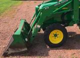 419 Loader
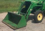 510 Loader
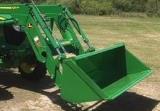 512 Loader
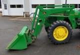 520 Loader
________________________________________________________________________________________
 520M Loader
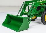 540M NSL
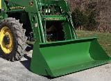 540 Loader
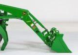 440R Loader
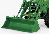 H180 Loader
________________________________________________________________________________________
 JD 5045E
 JD 5085E
 JD 5100M
 JD 6105R
 JD 6120M
________________________________________________________________________________________
 JD 6155M
 JD 6195R
 JD 6210R
 JD 7210R
 JD 7250R
________________________________________________________________________________________
 JD 7310R
 JD 8245R
 JD 8295R
 JD 8370R
 JD 9370R
________________________________________________________________________________________
 120R Loader
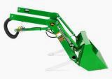 D120 Loader
 H120 Loader
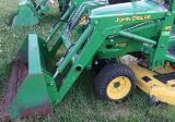 45 Loader
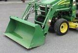 200CX Loader
________________________________________________________________________________________
 D160 Loader
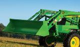 D170 Loader
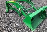 H160 Loader
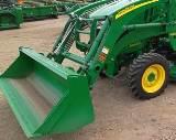 H165 Loader
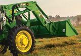 H240 Loader
________________________________________________________________________________________
 210 Loader
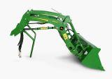 220R Loader
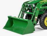 300E Loader
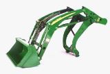 300X Loader
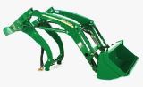 300CX Loader
________________________________________________________________________________________
 JD 9420R
 JD 9510R
 JD GX335
 JD GX85
 JD LA105
________________________________________________________________________________________
 JD 5065M
 JD 5055D
 JD 5115R
 JD 5105M
 JD 6110R
________________________________________________________________________________________
 JD 6130D
 JD 6225
 JD 7530
 JD 4044M
 JD 7185J
________________________________________________________________________________________
 300 Loader
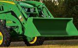 300R Loader
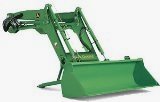 320R Loader
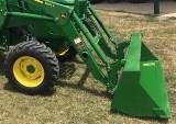 400E Loader
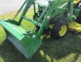 410 Loader
________________________________________________________________________________________
 430 Loader
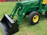 460 Loader
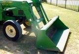 521 Loader
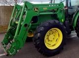 531 Loader
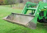 541 Loader
________________________________________________________________________________________
 551 Loader
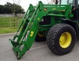 631 Loader
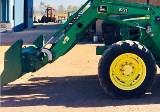 651 Loader
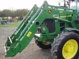 661 Loader
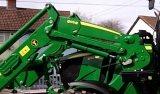 603R Loader
________________________________________________________________________________________
 JD D130
 JD D160
 JD 325
 JD 335
 JD 345
________________________________________________________________________________________
 JD 2520
 JD 3005
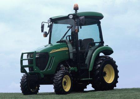 JD 3720
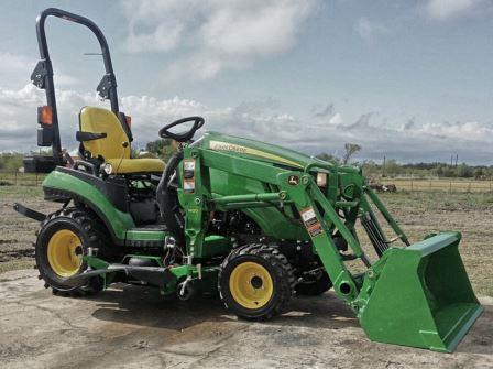 JD 1025R
 JD 3033R
________________________________________________________________________________________
 JD 5090EL
 JD 5100MH
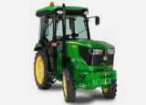 JD 5075GV
 JD 6090RC
 JD 6110B
________________________________________________________________________________________
 623R Loader
 643R Loader
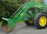 731 Loader
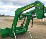 746 Loader
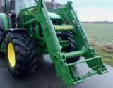 751 Loader
________________________________________________________________________________________
 533 Loader
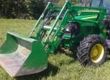 583 Loader
 633 Loader
 653 Loader
 683 Loader
________________________________________________________________________________________
 H260 Loader
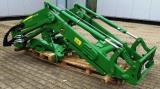 663R Loader
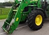 663 Loader
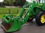 683R Loader
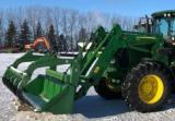 753 Loader
________________________________________________________________________________________
 JD 6125J
 JD 6150RH
 JD 6210J
 JD 7195J
 JD 8310
________________________________________________________________________________________
 JD 6325
 JD 5525
 JD 5083EN
 JD 5100GN
 JD 5125R
________________________________________________________________________________________
 210C Backhoe
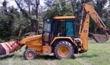 300D Backhoe
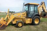 310G Backhoe
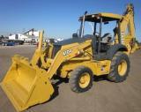 410G Backhoe
 710G Backhoe
________________________________________________________________________________________
 80 Loader
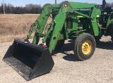 100 Loader
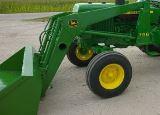 146 Loader
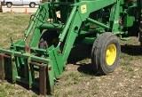 148 Loader
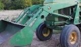 158 Loader
________________________________________________________________________________________
 168 Loader
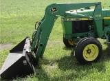 175 Loader
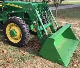 522 Loader
 542 Loader
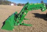 540R Loader
________________________________________________________________________________________
 562 Loader
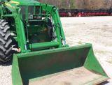 563 Loader
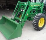 673 Loader
 741 Loader
________________________________________________________________________________________
 L108 Automatic
 L120 Automatic
 LA110 Automatic
 LA120 Automatic
 LA150 Automatic
________________________________________________________________________________________
 LT155
LT155 LT160 Automatic
 LT180 Automatic
 LTR180
 X165
X165________________________________________________________________________________________
 E100
E100 E120
E120 E150
E150 LTR166
________________________________________________________________________________________
 LA135
LA135 LA165
LA165 LX277
LX277 LX288
LX288 LX255
LX255________________________________________________________________________________________
 S240
S240 GT235
GT235 G110 Automatic
 JD 3203
 JD 5520
________________________________________________________________________________________
 JD 316
 JD 420
 JD 425
 JD 445
________________________________________________________________________________________
 JD_5050D
 X300
X300 X304
X304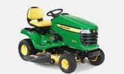 X310
X310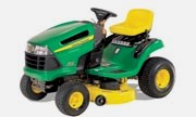 X110 Automatic
________________________________________________________________________________________
 H310 Loader
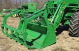 H340 Loader
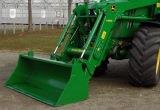 H360 Loader
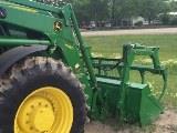 H380 Loader
 H480 Loader
________________________________________________________________________________________
 240 Loader
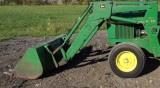 245 Loader
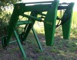 260 Loader
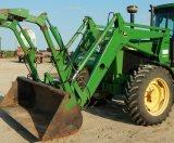 265 Loader
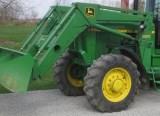 280 Loader
________________________________________________________________________________________
 600R Loader
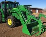 620R Loader
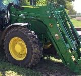 640R Loader
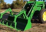 660R Loader
 680R Loader
________________________________________________________________________________________
 JD_5039D
 X146R
X146R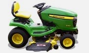 X360
X360 X155R
X155R X140 Automatic
________________________________________________________________________________________
 X350
X350 X380
X380 X500
X500 X590
X590 X700
X700________________________________________________________________________________________
 3036E
3036E 2038R
2038R 3038R
3038R 4049M
4049M JD 4100
________________________________________________________________________________________
 X738
X738 X740
X740 X748
X748 X749
X749 X950R
X950R________________________________________________________________________________________
 JD 4510
 5045D
5045D 5050E
5050E 5060E
5060E 5078E
5078E