________________________________________________________________________________
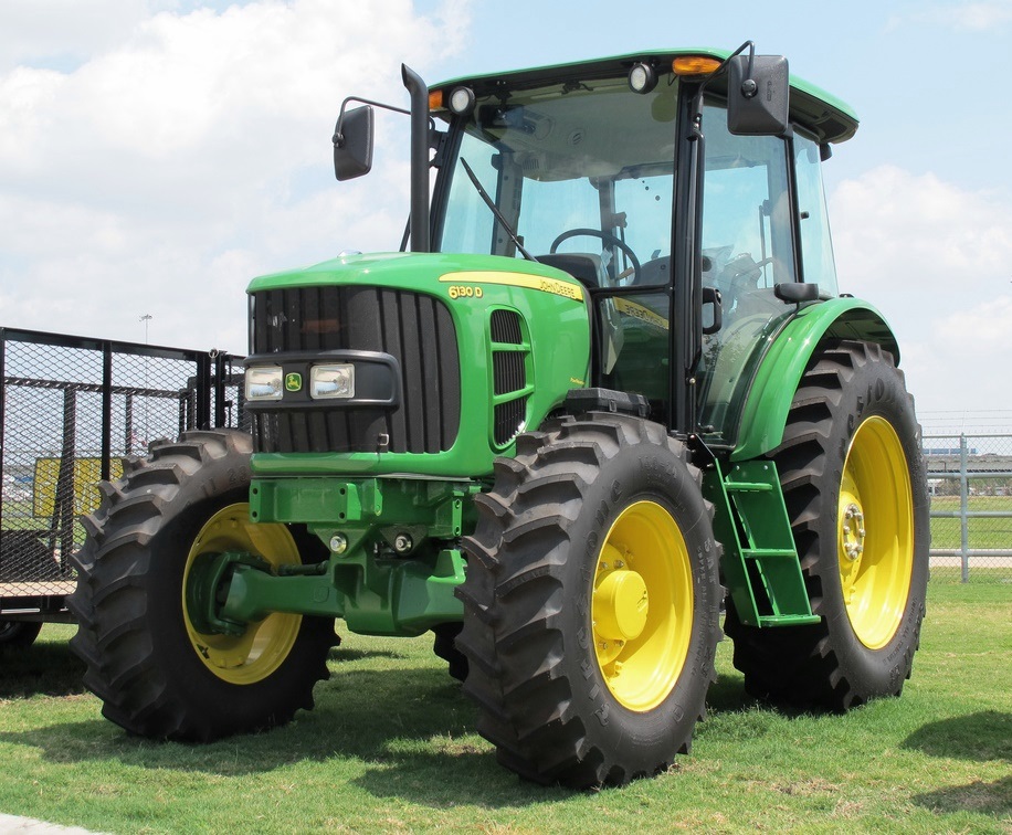
John Deere 1025R Attachments
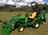
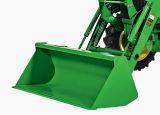
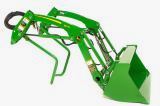
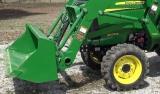
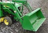
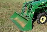
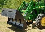
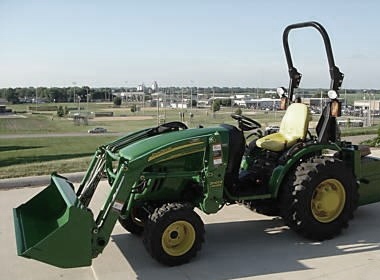
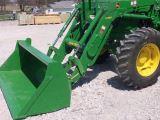
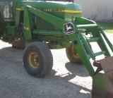
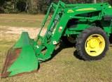
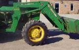
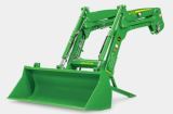
John Deere 1025R Front End Loader
120R Loader Specifications
Type of Attachment - Front End Loader
Compatibility - JD 1025R
Bucket Width - 1250 mm (49 in)
Bucket Mass - 70 kg (154 lb)
Hydraulic System Rated Flow - 26.5 L/min (7.0 gal/min)
Hydraulic System Maximum Pressure - 14 800 kPa (148 bar) (2146 psi)
Maximum Lift Height To Pivot Pin - 1828 mm (72 in)
Bucket Level Clearance - 1671 mm (66 in)
Bucket Dumped Clearance - 1371 mm (54 in)
Digging Depth - 82 mm (3 in)
Reach At Maximum Lift Height with Bucket Dumped - 626 mm (25 in)
Bucket Reach on Ground with Bucket Leveled - 1186 mm (47 in)
Dump Angle at Full Height - 41°
Dump Angle at Ground - 115°
Rollback Angle at Ground - 30°
Lift Capacity To Maximum Height at Pivot Point - 342 kg (754 lb)
Lift Capacity To Maximum Height at 500 mm (19.7 in) Forward of Pivot
Point - 236 kg (520 lb)
Lift Capacity To 1500 mm (59 in) at Pivot Pin - 337 kg (743 lb)
Breakout Force At Pivot Point - 826 kg-force (1823 lbf)
Breakout Force 500 mm (19.7 in) Forward of Pivot Point - 599 kg-force
(1320 lbf)
Loader Raise Time - 3.3 s.
Loader Lower Time - 3.2 s.
Bucket Dump Time - 3.1 s.
Bucket Rollback Time - 2.2 s.
Attaching 120R loader to John Deere
1025R tractor - Start the engine. Drive forward and
center John Deere 1025R tractor between the loader masts. Continue
forward aligning the loader masts with mounting frames. Pull forward
enough to be able to connect hydraulic hoses. Engage the park brake or
place the transmission in PARK. Relieve hydraulic pressure: Shut off the
engine and return the key to the ON position for electronically operated
control valves (tractor or loader with a third-function). Move the JD
120R loader controls (including the third-function control when
necessary) in all possible positions several times making sure that the
controls are returned back to the NEUTRAL position. Place the key in the
OFF position. Route the hose bundle into the hose guide.The anticipated
loader movement responds to the multi-function lever only if the hoses
are connected correctly.
Match the color-coded cap with the same color-coded plug. Connect
hydraulics JD 1025R tractor: Remove the protective cap from the hose and
the plug from the coupler. Push back the collar on the female coupler
and insert the male coupler. Connect the cap and plug together. Repeat
for all the remaining hose connections. Start the engine. If necessary,
continue to drive forward keeping pins on mounting frames in alignment
with notches in the masts. Place the transmission in NEUTRAL. Retract
lift cylinders. Masts lower onto mounting frames and parking stand
raises up below the weight bracket. Use a combination of extending
bucket cylinders and retracting lift cylinders until the loader masts
move back and latches lock over mounting frame bushings.
Remove Ballast Box -
Park machine on a hard, level surface. Engage the park brake or place
the transmission in PARK. Disengage the PTO. Shut off engine and remove
ignition key. 3-point hitch: Lower the ballast box to
the ground. Remove quick-lock pins from hitch pins and install in the
storage position on the tractor draft links. Remove the tractor draft
links from ballast box pins. Remove the quick-lock pin from the center
link. Position the tractor center link in the transport location.
Reinstall the center link pin and hardware. Start the engine and drive
the tractor away. Quick-hitch: Lower the ballast box so
it is slightly off the ground. Engage the park brake and place the
transmission in PARK. Raise both latch levers on the quick-hitch. Lower
the ballast box to the ground. Continue lowering the quick-hitch until
hooks clear ballast box pins. Start the engine and drive the tractor
away.
H120 Loader Specifications
Type of Attachment - Front End Loader
Compatibility - John Deere 1025R
Bucket Width - 125 cm (49 in.)
Bucket Weight - 51 kg (112 lb)
Hydraulic System Rated Flow - 13.2 L/min (2.9 gal/min)
Hydraulic System Maximum Pressure - 13700 kPa (137 bar) (1987 psi)
Loader Raise Time - 4.0 s.
Loader Lower Time - 2.5 s.
Bucket Dump Time - 5.7 s.
Bucket Rollback Time - 3.5 s.
Maximum Lift Height To Pivot Pin - 181 cm (71 in.)
Bucket Level Clearance - 165 cm (65 in.)
Bucket Dumped Clearance - 137 cm (54 in.)
Overall Length - 263 cm (103 in.)
Digging Depth - 10 cm (4 in.)
Reach At Maximum Lift Height with Bucket Dumped - 57 cm (22.5 in.)
Bucket Reach on Ground with Bucket Leveled - 117,6 cm (46 in.)
Maximum Dump Angle - 40 degrees
Maximum Dump Angle at Ground - 114 degrees
Maximum Rollback Angle - 31 degrees
Lift Capacity To Maximum Height at Pivot Point - 319 kg (703 lb)
Lift Capacity To Maximum Height - 232 kg (512 lb)
Lift Capacity To 150 cm (59 in.) at pivot pin - 331 kg (730 lb)
Lift Capacity To 150 cm (59 in.) - 265 kg (584 lb)
Breakout Force At Pivot Point - 782 kg-force (1724 lbf)
Breakout Force At 500 mm forward of pivot point - 595 kg-force (1312
lbf)
Bucket Rollback Force At maximum height - 763 kg-force (1682 lbf)
Bucket Rollback Force At 150 cm (59 in.) lift height - 789 kg-force
(1740 lbf)
Bucket Rollback Force At Ground Level Line - 867 kg-force (1912 lbf)
Attach Ballast Box to JD 1025R
Tractor with 3-Point Hitch - Back up John Deere 1025R
tractor to the ballast box with hitch points approximately in alignment.
Engage the park brake or place the transmission in PARK. Shut off engine
and remove ignition key. Attach the tractor draft links. Fasten with
quick-lock pins (stored on the tractor draft links). Align the center
link with the upper hole in mounting straps and install the center link
mounting hardware. Start the engine. Raise the ballast box. Check for
interference. Lower the hitch to the ground and adjust the center link
and/or lift links if necessary.
Attach and Detach Pin-On Bucket
- Bucket pins have two flat sides that must align with the inner bucket
hole. Spacers install on each side of the upper cylinder rods. Position
the tractor so the H120 loader boom aligns with the lower pin holes.
Engage the park brake and place the transmission in PARK. Shut off
engine and remove ignition key. Install the lower bucket pin and flange
nut. Start the engine. To align the cylinder rod with the upper hole,
use H120 loader controls. Shut off the engine. Install the upper pin
with spacers on each side of the cylinder rod. Tighten hardware to
specification. Flange Nut Torque - 150 Nm (110 lb-ft). Start the engine
and verify operation of the bucket functions. Detach the bucket in
reverse order.
Attach Ballast Box to 1025R Tractor
with Quick-Hitch - Lower the hitch until quick-hitch
hooks are lower than hitch pins. Back up the tractor to the ballast box.
Check spring-loaded clips on the quick-hitch to be sure that latches are
free and working properly. Make sure that latch control levers are down.
Raise the hitch engaging hitch pins in quick-hitch hooks. Raise the
ballast box and check for interference. Lower the ballast box to the
ground and adjust if necessary.
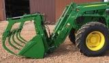
Root Grapple
53" Root Grapple Specifications
Model - Frontier AV20F Root Grapple
Overall Width - 53-inch (1480 mm)
Weight - 200 lbs
Compatibility - 200/300 Loader
Number of Tines - 5
Tine Spacing (in/mm) - 15 in. (381 mm)
Hydraulic Cylinders - 1
Bore x Stroke - 2.0 in. x 8.0 in. (50.8 mm x 203.2 mm)
Grapple Clamps - 1
Clamp Opening - 30.0 in. (760 mm)
Attach Root Grapple Frontier AV20F
- Extend bucket tilt cylinders to angle attaching brackets forward.
Angle must be greater than that of the brackets on the rear of the root
grapple. Drive forward, adjusting loader height and position until the
top of the loader bracket engages the hooks on the root grapple. Slowly
retract the bucket tilt cylinders and raise the loader so the lower lock
pins engage the hole in the holder strap. Continue to retract the tilt
cylinders and raise the loader until the main frame of the root grapple
is vertical. Engage tractor parking brake and/or place transmission in
PARK. Shut off tractor engine and remove key. Install the quick-lock-pin
into the pins on each side of the root grapple. Connect the hydraulic
hoses to the auxiliary hydraulic hook up on your loader or to the rear
tractor remote outlets. Start the tractor and lower the grapple clamp
arms. Installation is now complete.
John Deere 1025R Backhoe
260B Backhoe Specifications
Type of Attachment - Backhoe
Compatibility - John Deere 1025R
Digging Depth - 1890 mm (75 in)
Loading (Bucket at 60°) Height - 1524 mm (60 in)
Reach from Center Line of Swing Pivot - 2642 mm (104 in)
Transport Height - 1676 mm (66 in)
Loading Reach (Bucket at 60°) - 840 mm (33 in)
Transport Overhang Length - 940 mm (37 in)
Undercut Length - 43 cm (17 in.)
Bucket Rotation - 180°
Swing Arc Angle - 150°
Hydraulic Stabilizer Spread (Raised) Width - approx. 1473 mm (58 in)
Hydraulic Stabilizer Spread (Lowered) Width - approx. 1880 mm (74 in)
Boom Lift - 129 kg. (285 lb)
SAE Dipperstick Digging Force - 5280 N (1187 lbf)
SAE Bucket Digging Force - 9057 N (2036 lbf)
Buckets
20 cm (8 in.) Bucket Capacity (SAE Struck/Heaped) - 0.011 m3 (0.42 ft3)
/ 0.013 m3 (0.46 ft3)
30 cm (12 in.) Bucket Capacity (SAE Struck/Heaped) - 0.019 m3 (0.66 ft3)
/ 0.022 m3 (0.76 ft3)
41 cm (16 in.) Bucket Capacity (SAE Struck/Heaped) - 0.025 m3 (0.90 ft3)
/ 0.030 m3 (1.06 ft3)
Install Bucket -
Lubricate all pivot pins before installation. Align holes in bucket ears
with holes in dipperstick. Insert spacer, if necessary, between
dipperstick and bucket to minimize side-to-side clearance. Install pivot
pin. Secure with cap screw and nut. Tighten nut until cap screw threads
are extending past nut. Cap screw must not be tight. Align holes in
bucket with holes in link. Insert spacer, if required, between link and
bucket to minimize side-to-side clearance. Install pivot pin. Secure
with cap screw and nut. Tighten nut until cap screw threads extend past
nut.
Operating Mechanical 260B Backhoe
Thumb - The mechanical thumb can be used to pick up
objects and secure them between thumb and bucket. To operate the
mechanical thumb: Remove hitch pin. Slide column assembly to the desired
position. Secure using hitch pin and lock pin. When thumb is not in use,
it should be placed in the storage position. To place the mechanical
thumb in the storage position: Remove hitch pin. Slide column assembly
to its shortest position. Secure using hitch pin and cotter pin.
260B Backhoe Lubrication
- The following greases are recommended: Moly High Temperature EP
Grease, High Temperature EP Grease. Other greases that may be used: SAE
Multipurpose EP Grease with 3 to 5 percent molybdenum disulfide. SAE
Multipurpose EP Grease. Lubricate grease: Dipper
Cylinder Rod End. Upper and Lower Swing Pivot. Boom Cylinder Rod End.
Boom Pivot. Swing Pivot. Boom Cylinder Barrel End. Dipper Pivot. Guide
Link to Dipper Pivot. Guide Link to Bucket Link Pivot. Bucket Cylinder
Rod End. Bucket to Dipper Pivot. Bucket to Bucket Link Pivot. Add grease
until fresh grease exits joint. If fresh grease cannot enter pivot,
check for clogged grease path. Wipe excess grease from joint.
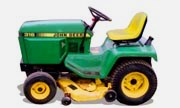
John Deere 1025R Mower Deck
54-inch Mower Deck Specifications
Model - 54D AutoConnect Mid-Mount Mower
Mower Type - Mulch or Side Discharge
Cutting Blades - 3
Overall Width - 1.74 m (68.5 in.)
Overall Length - 1.75 m (69 in.)
Cutting Height - 2.5-10.2 cm (1-4 in.)
Cutting Width - 1.37 m (54 in.)
Mower Weight - 89 kg (197 lb.)
Blade Bolt Torque - 68 Nm (50 lb-ft.)
Gearbox Oil Capacity - 136 mL (4.6 oz.)
60-inch Mower Deck Specifications
Model - 60D AutoConnect Mid-Mount Mower
Mower Type - Mulch or Side Discharge
Cutting Blades - 3
Overall Width - 1.85 m (72.8 in.)
Overall Length - 1.82 m (71.6 in.)
Cutting Height1 - 2.5-10.2 cm (1-4 in.)
Cutting Width - 1.52 m (60 in.)
Mower Weight - 117 kg (258 lb.)
Blade Bolt Torque - 122 Nm (90 lb-ft.)
Gearbox Oil Capacity - 136 mL (4.6 oz.)
Install 54D Mower -
If equipped, remove the front weights before installing the 54" mower
deck. Replace the weights after the mower deck is installed. Set the
mower height control to the install position. Raise handle to release
the lock on each gauge wheel. The mower rests fully on the ground.
Ensure that the mower deck is sitting on firm, level ground. A smooth
surface allows the mower to be pushed along by the tractor. Inflate
tires to 20 PSI. Ensure the rear lock assembly is in the locked
position. The lock assembly automatically unlocks as the machine engages
the mower, and locks after full engagement. Lower the mower lift arms
using the SCV or the rockshaft lever control. Shift the machine PTO
selector to the rear PTO to allow the mid-PTO and driveshaft to turn
freely and engage the mower gear case with minimal resistance.
Engage the tractor MFWD with the machine in low range. Drive the machine straight toward the rear of the mower while aligning the inside of the left front tire with the guide bar. Drive John Deere 1025R tractor onto the 54-inch mower deck with the inside of the left tire against the guide bar. Slowly drive the tractor forward until the mower begins to pull along ground for approximately 102 mm (4 inches) behind front wheels. If mower deck pulls forward early or appears to be caught in the lift system, stop the tractor, reverse slightly, and move forward again. If mower deck still does not properly attach, stop the tractor, lock the park brake, dismount the tractor, and determine the cause of the problem.
PTO coupler aligns with the gear box coupler. Dismount the tractor and
ensure locks on both sides have dropped to the locked position. If
necessary, pull the mower rearward to engage the lock and the coupler.
On first installation, mower may not lock in position if front link is
too short. Install the cotter pins in the locked position. Make sure the
forward lift link is nested into the hangers per specification. Forward
Lift Link Gap - 3 mm (0.125 in.). Start the engine and lift the mower to
full height. Pull the height lock fully forward and place the pin in the
nearest hole for transport or set the link to the desired height. Lock
down all gage wheels by snapping the handles down and ensuring the lock
pins are fully seated in the vertical rods.
John Deere 1025R Snowblower
47 Inch Front Mount Snowblower Specifications
Snow blower Type - 2-Stage, Front Mount
Compatibility - JD 1025R
Width - 1194 mm (47-inch)
Height of Opening - 584 mm (23-in.)
Housing Thickness - 14 ga (0.075-in.)
Side Panel Thickness - 7 ga (0.177-in.)
Auger Diameter - 16-in. (406 mm)
Auger Speed - 160 rpm at rated engine speed.
Impeller Speed - 800 rpm at rated engine speed.
Impeller Diameter - 406 mm (16-in.)
Lift System - Hydraulic
Lift Height - 191-203 mm (7-1/2-8 in.)
Chute Control - Hydraulic
Chute Rotation - 200 Degrees
Weight (Approximate) - 181 kg (400 lb)
54 Inch Front Mount Snowblower Specifications
Type - Front-Mount
Compatibility - JD 1025R
Clearing Width - 1.40 m (54 inch)
Height to Top of Spout - 78 cm (30-5/8 in.)
Length - 69 cm (27 in.)
Lift Height - 279 mm (11 in.)
Net Weight - 113 kg (250 lb.)
Scraper Blade Reversible and Replaceable - 1.3 m (59-15/16 in.)
Discharge Chute Control - Hydraulic
Discharge Chute Rotation - 100° to each side
Snowblower Drive - Splined coupler shaft to gear case
Snowblower Lift - Hydraulic
Rotor Length - 1 m (39-3/8 in.)
Auger Speed - 176 rpm
Auger Diameter - 40.6 cm (16 in.)
Impeller Speed - 950 rpm
Impeller Diameter - 40.3 cm (15.5 in.)
Drive - Gear case to roller chain
Bearings - Sealed ball bearings
Install Discharge Chute
- Put light coat of John Deere Moly High Temperature EP Grease or an
equivalent onto discharge chute base and install discharge chute.
Install three large clips with six self-tapping screws (M8x20). Tighten
screws. Chute should rotate freely after tightening.
Install Discharge Chute Cables
- Lay cables over attachment shell. Hydraulic cylinder plunger must be
in the retracted position (all the way in the cylinder) when beginning
this procedure. Remove black cable shield and bracket. Verify that
cables are still on pulleys. Rotate chute right. Stand behind
attachment. Take right cable and wrap around chute counterclockwise. Use
locking pliers and pull cable tight around threaded stud, and behind
locknut and washer. Tighten nut. Wrap left cable around chute clockwise.
Use locking pliers and pull cable tight around threaded stud, and behind
locknut and washer. Tighten nut. Tuck excess ends of cables under cable.
Make sure that you install the long cap screw through the black cable
shield and bracket. Install black cable shield and bracket.
Install 54" Snow blower Driveshaft
- Lubricate driveshaft grease fittings with Moly High Temperature EP
Grease or an equivalent. Extend and retract driveshaft to cycle grease
across driveshaft. Apply additional grease as needed. Shield has been
removed for clarity. Install woodruff key in the gear case shaft groove.
Apply NEVER-SEEZ lubricant or equivalent on sprocket shaft. Align groove
in driveshaft with the key on the sprocket shaft and push driveshaft on
sprocket shaft. Align holes on the sprocket shaft with holes in
driveshaft and install the rolled pin through both shafts. Install
plastic coated retainer wire through rolled pin and twist both ends of
wire together a minimum of three times.
54-inch Rear Snow blower Specifications
Model - Frontier SB1154
Type - Rear-Mount
Compatibility - JD 1025R
Hitch Type - Cat. 1 iMatch
Steel skid shoes - Adjustable and replaceable
Cutting edge - Welded
Park Stand - Standard
Chute type - Two part
Chute deflector - Manual standard
Optional deflector adjustment - 3000 psi. (14,647 kPa)
Chute rotation - Manual or hydraulic 245 degrees
Working height - 26 in. (66.0 cm)
Transport width - 54 in. (137.2 cm)
Working width - 54 in. (137.2 cm)
Length - 41 in. (104.1 cm)
Roller chain - #60
Chain idler adjustment - Manual
Chute diameter - 8 in. (20.3 cm)
Auger diameter - 15 in. (38.1 cm)
Auger speed - 170 RPM
Impeller speed - 540 RPM
Impeller blades - 4
Impeller diameter - 24 in. (61.0 cm)
Tractor PTO speed - 540 RPM
Minimum tractor HP - 20 PTO HP
Maximum tractor HP - 40 PTO HP
Auger overload protection - Shearbolt
PTO overload protection - Shearbolt
Operating weight - 512 lb. (232.2 kg)
Shipping weight - 514 lb. (233.1 kg)
Installation of SB1154 Snowblower
with Three Point Hitch - Remove nut and lockwasher from
the cat.1 lower hitch pins. Place the jam nut so to obtain 1.38" (35 mm)
minimum between edge of the hole of lower hitch pin and jam nut. Insert
the lower hitch pins in lower hole of the hitch and secure with
lockwasher and nut. Install the eyebolt in upper hole of left or right
side of the three point hitch by screwing the eyebolt nut to the top and
locking eyebolt in place with a 3/8"serrated flange nut. Attach tractor
lower links to the hitch pins and secure with linchpins. Attach the
tractor upper link between the upper attaching plates using the tractor
pin and linchpin. Adjust 54-inch snow blower using the tractor upper
link as to bring the snow blower parallel to ground level. Set the
tractor anti-sway turnbuckles so the snowblower does not sway. Be sure
there is no contact with the tires.
John Deere 1025R Blade and Rotary Broom
60 Inch Blade Specifications
Model - 60" Quick Hitch Front Blade
Width, Straight - 60 in. (1520 mm)
Width, Angled 15° - 58 in. (1470 mm)
Width, Angled 27° - 53.5 in. (1350 mm)
Angling Positions, Right and Left - 0-27 deg.
Blade Trip - Spring Trip
Blade Float - Hydraulic
Required Equipment:
Front Hitch Kit. Selective Control Valve Kit. Hydraulic Angling Kit.
Front Attaching Support Kit. Cat 1N A-frame.
Installing 60" Front Blade to Front
Hitch - Place Blade on level surface. Lower front hitch.
Pull out locking pin lever. Locking pin lever on each side of front
hitch bracket must be in the unlatched position. Move machine forward
slowly until slot on front hitch bracket lines up with pin on front
blade. Raise front hitch until slot locks into place under pin and
locking pins. Lower front blade to the ground and park machine. Visually
inspect to ensure both pins are fully engaged.
Replacing Cutting Edge
- Replace the blade when edge becomes worn, rough, or bent. Raise the
blade. Put blocks under each end of blade. Lower the blade to rest on
blocks. Lock park brake, stop engine and remove key. Remove nuts,
washers and bolts (12). Remove and replace cutting edge. Install bolts,
washers and nuts. Torque to specification.
Replacing Skid Shoes
- Raise 60" front blade. Put blocks under each end of blade. Lower the
blade to rest on blocks. Lock park brake, stop engine and remove key.
Remove spring locking pin. Remove Pin. Remove and replace one or both
skid shoes as required. Skid shoes must be at same height on both sides
of blade. Reinstall pin and spring locking pin.
60 Inch Rotary Broom Specifications
Compatibility - JD 1025R
Overall Broom Height - 77 cm (30.5 in)
Overall Broom Width - 1.6 m (62 in)
Sweeping width when angled 0° - 1.5 m (57 in)
Sweeping width when angled 30° left or right - 1.3 m (50 in)
Brush Diameter - 66 cm (26 in)
Brush Material - Polypropylene and Steel
Sections - 32
Angling - 0-30° Each Side
Angling Method - Hydraulic
Speed - 200 rpm
Caster Wheels - 160 x 80 mm (6-1/4 x 3-1/4 in.)
Brush Drive - Front PTO
Broom Gearbox Reduction - 3 to 1, Straight Bevel Gear, Shear Pin
Protected
Final Drive - Chain and sprocket, core sprocket taper lock hub
Weight - 203 kg 448 lb
Attach 60-inch Rotary Broom to Front
Quick Hitch - Remove PTO shaft support from storage hook
on mounting frame. Swing shaft support toward center of broom frame and
position. Place PTO shaft onto support. Align broom mounting frame with
front quick hitch. Rotate and release both L-pins. Start John Deere
1025R tractor engine. Push SCV control lever forward until notches in
front quick hitch are lower than pins on mounting frame. Drive machine
forward slowly to engage pins into notches. Pull the SCV control lever
rearward to raise front quick hitch. Make sure pins drop into
notches.Lower the hitch until L-pins snap into holes at sides of broom
mounting frame. Park the machine safely. Check engagement of L-pins.
Adjust as needed.
60" Rotary Broom Removal
- Install parking stands in lowered position. Lower broom on gauge
wheels and parking stands. Pull back collar on PTO shaft coupler. Pull
driveshaft straight back until it disconnects from PTO output shaft. Put
PTO shaft support in support position. Put PTO shaft on support. Pull
both L-pins outward and turn to unlocked position with roll pins in
grooves. Push lower hydraulic control lever on tractor forward to lower
front hitch. Drive tractor back slowly until notches in hitch disengage
from pins on broom frame. Remove any ballast.
Adjust Chain Tension
- Lower brush head until bristles are approximately 76 mm (3 in.) off
the ground. Support brush head in raised position with wood blocks or a
safe lifting device. Disconnect front driveshaft from machine: Pull back
coupler. Pull broom driveshaft off of front hitch PTO stubshaft. Loosen
jam nut. While rotating brush manually, turn adjustment bolt clockwise
by hand until it will not tighten any more. Tighten jam nut.
Adjust 60" Rotary Broom
- Unlock the Angle Lock - Remove lock pin from angle lock position.
Install lock pin into storage position. Raise Parking Stands - Install
broom parking stands in raised position. Level broom to set height of
stands. Level Broom - Check tire air pressures. Park machine safely.
Verify that broom is in float position. Swing plate on front quick hitch
should be horizontal or parallel to ground with installed broom in float
position. If broom is level, no adjustment needed. If broom is not
level, determine how far you need to raise or lower broom wheels to
level broom, and adjust broom wheel height. Adjust Wheel Height -
Support wheel yoke. Remove quick-lock pin. Each spacer provides 13 mm
(1/2 in.) of broom height adjustment. Adjust wheel spacers: Move spacers
to top of spindle to lower brush head. Move spacers to bottom of spindle
to raise brush head. Install quick-lock pin. Repeat for other side.
John Deere 1025R Rotary Cutter and Rotary
Tiller
647 Rotary Tiller Specifications
Model - 647 Rotary Tiller
Compatibility - JD 1025R
Cutting Width - 120 cm (48 in.)
Tilling Depth - 18 cm (7 in.)
Skid Shoe Height Adjustment - 3,0-7,5 cm (1.2-3 in.)
Number of Tines - 36
Tine Cutting Diameter - 38 cm (15 in.)
Tine Shaft Speed - 253 rpm
Final Drive Chain - ASA 60 HE
Gearbox Fluid Capacity - 0,750L (1.7 pt)
Chaincase Fluid Capacity - 1,100L (2.5 pt)
Drive Type - PTO
Number of Flanges - 6
Skid Shoes - Standard
Parking Stand - Standard
Width, Overall (in.) - 52 in
Weight (less slip clutch and joint) - 135kg (298 lb)
PTO Driveline Lubricating
- Lubricate grease fitting on U-joints at both ends. Lubricate shield
grease fitting at both ends. Separate driveline and apply grease to
inner shaft.
Checking and Changing Gearbox Oil
- To add oil: Remove check plug on top of gear box. Add gear oil until
visible on the dipstick. Install and tighten check plug to 25 Nm (17.5
lb-ft). To change oil: Remove 647 Rotary Tiller tiller from machine.
Locate and remove drain plug from bottom of gearbox. On 647 model,
remove the guard and the PTO driveline from the tiller to access the
drain plug. Drain all oil. Install and tighten drain plug to 25 Nm (17.5
lb-ft). Install PTO driveline and guard if removed. Remove check plug on
top of gear box. Add gear oil until visible on the dipstick. Install and
tighten check plug to 25 Nm (17.5 lb-ft).
RC2048 Rotary Cutter Specifications
Model - Frontier RC2048 Rotary Cutter
Compatibility - JD 1025R
Cutting Width, in. (mm) - 48 (1220)
Cutting Height, in. (mm) - 1.5 to 9 (38 to 229)
Cutting Capacity (diameter), in. (mm) - 0 to 1 (0 to 25)
Cutting Chamber Depth, in. (mm) - 7.5 (190)
Hitch Type - Lift-Type
Hitch Category - 1, iMatch/Autohitch
Overall Width, in. (mm) - 51 (1291.4)
Overall Length, in. (mm) - 86.6 (2199.6)
Deck Shape - Flat-open round back
Deck Type - Single
Approx. Weight, lb. (kg) - 516 (234)
Deck Thickness, gauge (mm) - 11 (3)
Skirt Thickness, gauge (mm) - 11 (3)
Driveline Type - Shear Bolt or Slip Clutch
Gearbox HP Rating - 45
Blades Thickness, in. (mm) - 0.5 (13)
Blades Width, in. (mm) - 3 (76)
Blades Type - Heat Treated Suction
Blade Tip Speed, ft./min. (m/s) - 13,090 (66.5)
Blade Holder Type - Round pan-type
Blade Holder Diameter, in. (mm) - 22.3 (567)
Wheels Type - Solid Rubber or Laminated
Diameter Laminated, in. (mm) - 15 (381)
Width Laminated, in. (mm) - 3.75
Diameter Rubber, in. (mm) - 15 (381)
Width Rubber, in. (mm) - 3.75 (95.25)
Attaching RC2048 Rotary Cutter to
1025R Tractor with Three-Point Hitch - Back up tractor
to cutter with hitch points approximately in alignment. Engage tractor
parking brake and/or place transmission in “Park”. Shut off tractor
engine and remove key. Remove center link mounting hardware and hitch
pin assemblies at both hitch masts. Install tractor draft links on hitch
pins. Secure with quick-lock pins (stored on tractor draft links.) Align
center link with upper hole in cutter mast straps and install center
link mounting hardware. Start tractor engine. Slowly pull hitch control
lever to raise cutter. Check for interference. Lower hitch to ground and
adjust center link and/or lift links if necessary.
________________________________________________________________________________
 JD SPECS
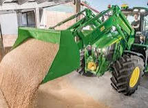 JD LOADERS
 JD MAINTENANCE
 JD INSTRUCTIONS
 JD PROBLEMS
________________________________________________________________________________________
 JD 2025R
 JD 3039R
 JD 4044R
 JD 4105
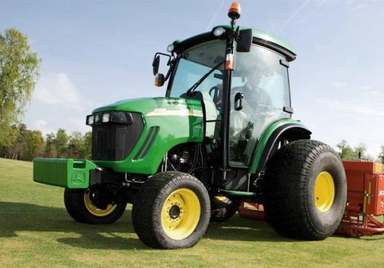 JD 4720
________________________________________________________________________________________
 420 Loader
 419 Loader
 510 Loader
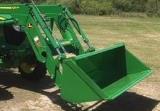 512 Loader
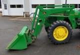 520 Loader
________________________________________________________________________________________
 520M Loader
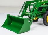 540M NSL
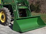 540 Loader
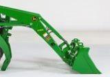 440R Loader
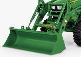 H180 Loader
________________________________________________________________________________________
 JD 5045E
 JD 5085E
 JD 5100M
 JD 6105R
 JD 6120M
________________________________________________________________________________________
 JD 6155M
 JD 6195R
 JD 6210R
 JD 7210R
 JD 7250R
________________________________________________________________________________________
 JD 7310R
 JD 8245R
 JD 8295R
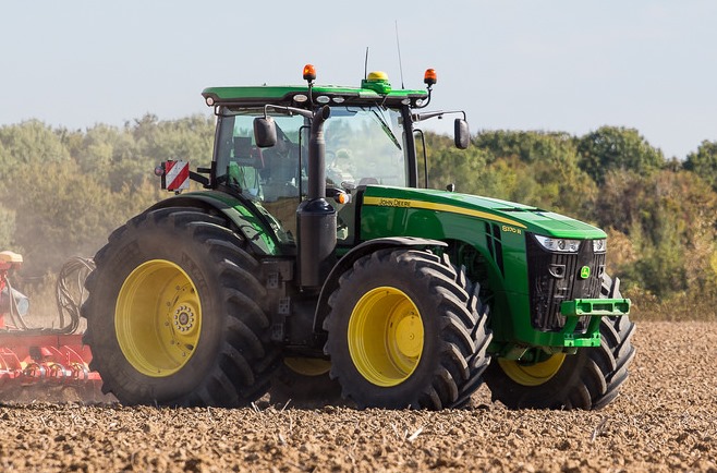 JD 8370R
 JD 9370R
________________________________________________________________________________________
 120R Loader
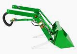 D120 Loader
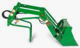 H120 Loader
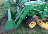 45 Loader
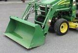 200CX Loader
________________________________________________________________________________________
 D160 Loader
 D170 Loader
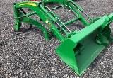 H160 Loader
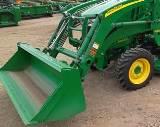 H165 Loader
 H240 Loader
________________________________________________________________________________________
 210 Loader
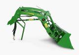 220R Loader
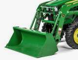 300E Loader
 300X Loader
 300CX Loader
________________________________________________________________________________________
 JD 9420R
 JD 9510R
 JD GX335
 JD GX85
 JD LA105
________________________________________________________________________________________
 JD 5065M
 JD 5055D
 JD 5115R
 JD 5105M
 JD 6110R
________________________________________________________________________________________
 JD 6130D
 JD 6225
 JD 7530
 JD 4044M
 JD 7185J
________________________________________________________________________________________
 300 Loader
 300R Loader
 320R Loader
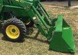 400E Loader
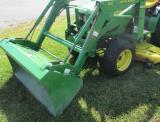 410 Loader
________________________________________________________________________________________
 430 Loader
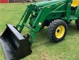 460 Loader
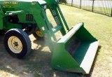 521 Loader
 531 Loader
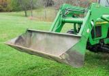 541 Loader
________________________________________________________________________________________
 551 Loader
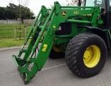 631 Loader
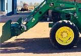 651 Loader
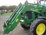 661 Loader
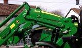 603R Loader
________________________________________________________________________________________
 JD D130
 JD D160
 JD 325
 JD 335
 JD 345
________________________________________________________________________________________
 JD 2520
 JD 3005
 JD 3720
 JD 1025R
 JD 3033R
________________________________________________________________________________________
 JD 5090EL
 JD 5100MH
 JD 5075GV
 JD 6090RC
 JD 6110B
________________________________________________________________________________________
 623R Loader
 643R Loader
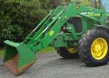 731 Loader
 746 Loader
 751 Loader
________________________________________________________________________________________
 533 Loader
 583 Loader
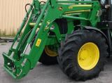 633 Loader
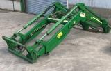 653 Loader
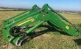 683 Loader
________________________________________________________________________________________
 H260 Loader
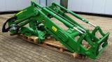 663R Loader
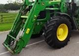 663 Loader
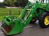 683R Loader
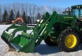 753 Loader
________________________________________________________________________________________
 JD 6125J
 JD 6150RH
 JD 6210J
 JD 7195J
 JD 8310
________________________________________________________________________________________
 JD 6325
 JD 5525
 JD 5083EN
 JD 5100GN
 JD 5125R
________________________________________________________________________________________
 210C Backhoe
 300D Backhoe
 310G Backhoe
 410G Backhoe
 710G Backhoe
________________________________________________________________________________________
 80 Loader
 100 Loader
 146 Loader
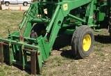 148 Loader
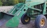 158 Loader
________________________________________________________________________________________
 168 Loader
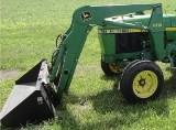 175 Loader
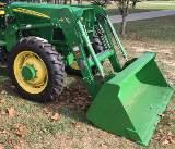 522 Loader
 542 Loader
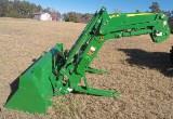 540R Loader
________________________________________________________________________________________
 562 Loader
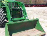 563 Loader
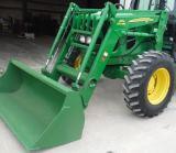 673 Loader
 741 Loader
________________________________________________________________________________________
 L108 Automatic
 L120 Automatic
 LA110 Automatic
 LA120 Automatic
 LA150 Automatic
________________________________________________________________________________________
 LT155
LT155 LT160 Automatic
 LT180 Automatic
 LTR180
 X165
X165________________________________________________________________________________________
 E100
E100 E120
E120 E150
E150 LTR166
________________________________________________________________________________________
 LA135
LA135 LA165
LA165 LX277
LX277 LX288
LX288 LX255
LX255________________________________________________________________________________________
 S240
S240 GT235
GT235 G110 Automatic
 JD 3203
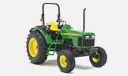 JD 5520
________________________________________________________________________________________
 JD 316
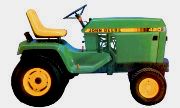 JD 420
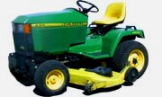 JD 425
 JD 445
________________________________________________________________________________________
 JD_5050D
 X300
X300 X304
X304 X310
X310 X110 Automatic
________________________________________________________________________________________
 H310 Loader
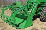 H340 Loader
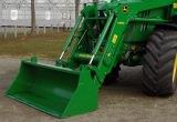 H360 Loader
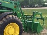 H380 Loader
 H480 Loader
________________________________________________________________________________________
 240 Loader
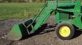 245 Loader
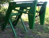 260 Loader
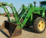 265 Loader
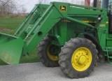 280 Loader
________________________________________________________________________________________
 600R Loader
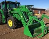 620R Loader
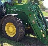 640R Loader
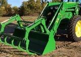 660R Loader
 680R Loader
________________________________________________________________________________________
 JD_5039D
 X146R
X146R X360
X360 X155R
X155R X140 Automatic
________________________________________________________________________________________
 X350
X350 X380
X380 X500
X500 X590
X590 X700
X700________________________________________________________________________________________
 3036E
3036E 2038R
2038R 3038R
3038R 4049M
4049M JD 4100
________________________________________________________________________________________
 X738
X738 X740
X740 X748
X748 X749
X749 X950R
X950R________________________________________________________________________________________
 JD 4510
 5045D
5045D 5050E
5050E 5060E
5060E 5078E
5078E