________________________________________________________________________________
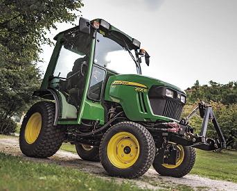
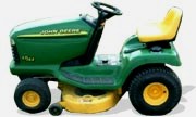
John Deere 2210 Attachments

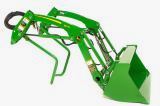
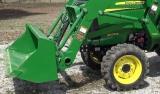
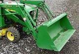
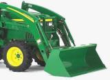
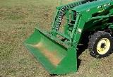
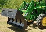
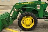
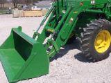
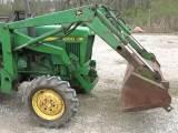
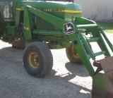
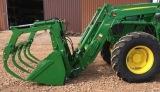
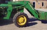
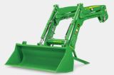
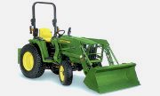
John Deere 2210 Front End Loader
210 Loader Specifications
Type of Attachment - Front End Loader
Compatibility - John Deere 2210
Bucket Width - 1250 mm (49.2 in.)
Bucket Length - 618 mm (24.3 in.)
Bucket Mass - 70 kg (154 lb)
Hydraulic System Rated Flow - 20.8 L/Min (5.5 gal/min)
Hydraulic Maximum Pressure - 13,700 kPa (137 bar) (1987 psi)
Maximum Lift Height To Pivot Pin - 1740 mm (68.5 in.)
Bucket Level Clearance - 1582 mm (62 in.)
Bucket Dumped Clearance - 1280 mm (50 in.)
Overall Length - 2725 mm (107.2 in.)
Digging Depth - 200 mm (7.9 in.)
Reach At Max Lift Height - 615 mm (24.2 in.)
Bucket Reach on Ground - 1275 mm (50.2 in.)
Max Dump Angle - 47.2°
Max Dump Angle at Ground - 124°
Max Rollback Angle - 26.5°
Rollback Angle at Full Height - 98.2°
Overall Height In Carry Position - 1105 mm (43.5 in.)
Lift Capacity To Max Height at Pivot Point - 282 kg (622 lb)
Lift Capacity To Max Height - 198 kg (437 lb)
Lift Capacity To 1.5 m (59 in.) at Pivot Point - 327 kg (721 lb)
Lift Capacity To 1.5 m (59 in.) - 236 kg (520 lb)
Lift Capacity With Forklift to Max Height - 234 kg (516 lb)
Breakout Force At Pivot Point (Y) - 7017 N (1577 lb force)
Breakout Force 500 mm (19.7 in.) Forward of Pivot Point - 4768 N (1072
lb force)
Bucket Rollback Force At Max Height - 5750 N (1293 lb force)
Bucket Rollback Force At 1.5 m (59 in.) Lift Height - 6621 N (1488 lb
force)
Bucket Rollback Force At Ground Level Line - 7343 N (1650 lb force)
Hydraulic Lift Cylinder (Bore/Stroke) - 40 mm (1.6 in.) / 342 mm (13.5
in.)
Hydraulic Lift Cylinder (Bore/Stroke) - 25 mm (1.0 in.) / 541 mm (21.3
in.)
Hydraulic Bucket Cylinder (Rod Diameter/Closed Length) - 40 mm (1.6 in.)
/ 404 mm (15.9 in.)
Hydraulic Bucket Cylinder (Rod Diameter/Closed Length) - 25 mm (1.0 in.)
/ 611 mm (24.1 in.)
Loader Raising Time - 3.8 s
Loader Lowering Time - 2.0 s
Bucket Dumping Time - 2.4 s
Bucket Rollback Time - 3.4 s
Attaching John Deere 210 Loader
- Drive tractor slowly, straight into 210 loader. Align masts with rear
frames. Engage JD 2210 tractor parking brake and/or place transmission
in "Park". Shut off tractor engine and remove key. Move multi-function
control lever back and forth and side-to-side several times to relieve
hydraulic system pressure. Route hydraulic hoses through guide. Connect
colored couplers on hoses matching numbers and/or colors on decal by
coupler plate.
Dust Cap Color - Yellow. Hydraulic Function - Bucket Cylinder-Rod End
(Port 1)
Dust Cap Color - Silver. Hydraulic Function - Bucket Cylinder-Head End
(Port 2)
Dust Cap Color - Green. Hydraulic Function - Lift Cylinder-Head End
(Port 4)
Dust Cap Color - Black. Hydraulic Function - Lift Cylinder-Rod End (Port
3)
Slowly retract lift cylinders. Masts will lower into mounting frames. Be
sure notches in bottom of masts align with tab on each mounting frame.
Fully retract lift cylinders raising front wheels slightly off ground.
Latch bar will raise into slot in front weight bracket. Engage JD 2210
tractor parking brake and/or place transmission in "Park". Shut off
tractor engine and remove key. Pull back on lock handles and turn into
locking position. To help prevent damage to loader and/or tractor, be
sure latch bar is fully engaged. This holds front of 210 loader onto
tractor. Check to be sure latch bar and lock handles are "FULLY"
engaged. Start tractor engine. Extend lift cylinders to lower tractor to
ground. Add appropriate ballast.
Attaching and Detaching Bucket or
Forklift - Roll bucket back slightly and raise boom
approximately 460 mm (18 in.) above ground level. Remove pin from each
side of attachment. Store pins in storage position. Extend bucket
cylinders until pin releases from strap on each side of attachment.
Lower 210 loader boom and reverse away from attachment. Carrier will
release from hook on each side of attachment. To attach attachment,
reverse the above steps.
Tines for Material Buckets
- Bucket tines are not compatible with 1250 mm (49 in.) bucket. Use
tines to penetrate hard-packed materials and to handle manure or silage.
Tines extend approximately 305 mm (12 in.) from cutting edge. Holes must
be drilled into bucket to accept tines.
Installing Hitch Pin Bushings on
Ballast Box for Category 1 Quick Coupler Hitch - Install
bushings on both hitch pins. Install small bushing over hitch pin with
cross hole. Install large bushing. Align holes in bushings with hole in
hitch pin and install spring pin. Assemble bushings. Insert center link
pin through ballast box mast and bushing assembly. Fasten with
quick-lock pin.
Attaching Ballast Box to JD 2210
Tractor with Three-Point Hitch - Back up tractor to
ballast box with hitch points approximately in alignment. Engage tractor
parking brake and/or place transmission in "Park". Shut off tractor
engine and remove key. Attach tractor draft links. Fasten with
quick-lock pins (stored on tractor draft links). Align center link with
upper hole in ballast box mounting straps and install center link
mounting hardware. Start tractor engine. Slowly pull hitch control lever
to raise ballast box. Check for interference. Lower hitch to ground and
adjust center link and/or lift links if necessary.
Check and Adjust Latch Bar Alignment
- Lower 210 loader to the ground and apply enough downward force to
relieve weight of tractor from front tires. Latch bar assembly should
raise into position. If latch bar assembly
raises into position - Rotate lock handles to latch loader to tractor.
Tighten mounting frame hardware to specifications. If latch bar assembly
does not raise into position, (lock handles aligned/engaged) - Position
latch bar, using lift cylinders, until just below slot. Loosen M16
hardware (both sides) and adjust latch bar until it is centered in slot.
Retract lift cylinders to raise bar fully into position. If necessary,
use a clamp to raise bar into position. Tighten hardware (including
mounting frame hardware) to specifications. M16 Hardware Torque 350 Nm
(225 lb-ft). Mounting Frame Hardware Torque 140 Nm (105 lb-ft).
John Deere 2210 Backhoe
260 Backhoe Specifications
Type of Attachment - Backhoe
Compatibility - John Deere 2210
Digging depth 2-ft. (610 mm) flat bottom - 6-ft. 2-in. (1.9 m)
Swing arc - 150 degree
Loading height (bucket at 60 degree) - 5-ft. (1.5 m)
Reach from center line of swing pivot - 8-ft. 8-in. (2.6 m)
Transport height (maximum) - 6-ft. 6-in. (1.7 m)
Bucket rotation - 180 degrees
Loading reach (bucket at 60 degree) - 2-ft. 9-in. (0.8 m)
Transport overhang - 3-ft. 1-in. (0.9 m)
Undercut - 1-ft. 5-in. (0.4 m)
Hydraulic stabilizer spread, down (approx.) - 6-ft. 2-in. (1.9 m)
Hydraulic stabilizer spread, up (approx.) - 4-ft. 10-in. (1.5 m)
Boom lift ability - 285 lb. (129 kg)
SAE dipperstick digging force - 1187 lbf. (5280 N)
SAE bucket digging force - 2036 lbf. (9056 N)
Backhoe weight with 16-in. bucket - 610 lb. (277 kg)
Angle of departure - 20 degree
How to Install and Remove a 260
Backhoe on John Deere 2210 Tractor
Installation - Back up your tractor to the backhoe
(within 8 inches). Set tractor into park position. Route the hydraulic
hoses from the backhoe through the guide and connect to the hydraulic
hoses from the tractor. Remove backhoe boom lock pin. Back the JD 2210
tractor closer to the backhoe - Use backhoe control levers to align the
backhoe frame with the backhoe mounts on the tractor. Use pins to secure
the 260 backhoe to the tractor. Use stabilizer controls to raise and
lower stabilizers as needed - Position notches in backhoe frame above
the mount hooks. Use the stabilizers to lower the attaching hooks onto
the notches on the back of the tractor. Use the boom controls to raise
the boom into the back of the tractor - Install pins to secure the
backhoe to the tractor.
Removal - Lower stabilizers to within a few inches
above the ground. Center the boom and install the swing locking pin
(Remove boom locking pin if installed). Extend the dipper stick and
lower the boom. Rotate the backhoe bucket until the top edge of the
bucket is parallel with the ground. Use the boom control lever to lower
the boom, placing a slight downward pressure on the 260 backhoe. Remove
the connecting pins from the backhoe mounts. Use the backhoe controls to
lower the backhoe to just a few inches above the ground. Use the
stabilizer controls to life the backhoe off the lower mounting notches
on the tractor. Lower backhoe all the way to the ground. Disconnect all
of the hydraulic hoses from the backhoe to the tractor - closing the
connectors on both the tractor and backhoe.
John Deere 2210 Mower Deck
54-inch Mower Deck Specifications
Model - 54C Mid-Mount Mower Deck
Mower Type - Mulch, Bag or Side Discharge
Compatibility - John Deere 2210
Cutting Blades - 3
Mower Weight - 77 kg (170 lb)
Blade Bolt Torque - 68 Nm (50 lb-ft)
Cutting Width - 137.2 cm (54 in.)
Cutting Height (approximate) - 25-127 mm (1 to 5 in.)
Height Adjustment - 13 position, 6.35 mm (1/4 in.)
62-inch Mower Deck Specifications
Model - 62C Mid-Mount Mower Deck
Mower Type - Mulch, Bag or Side Discharge
Compatibility - JD 2210
Cutting Blades - 3
Mower Weight - 91 kg (200 lb)
Blade Bolt Torque - 68 Nm (50 lb-ft)
Cutting Width - 157.5 cm (62 in.)
Cutting Height (approximate) - 25-127 mm (1 to 5 in.)
Height Adjustment - 13 position, 6.35 mm (1/4 in.)
Install Mower Discharge Chute
- Hold chute firmly on 62C mower deck when installing. Install mower
discharge chute to mower deck with two bolts and lock nuts. Tighten nuts
to 20 Nm (15 lb-ft). Check hinge action by opening and releasing the
chute. The chute must spring back completely to the lowered position.
Install Mower Deck Gauge Wheels
- Remove gauge wheels by pulling back on release rod. Insert gauge
wheels, wheel down. Pull and hold release rod, move wheel to desired
position. Insert release rod in hole.
Check Height of Lift Arms
- 54C Mower height control knob must turn 360 deg. If knob does not turn
360 deg, adjust height. Start machine and pull back rockshaft control
lever to raise arms. Turn mower height control knob 360 deg. If knob
does not turn, push rockshaft control lever forward to lower arms. Stop
machine. Loosen nuts on both sides of lift rod assembly. Turn lift rod
assembly to lengthen distance between points, the centerline of yoke
holes, to 625 mm (24.6 in.). Hand tighten nuts. Start machine and pull
back rockshaft control lever to raise arms. Turn mower height control
knob 360 deg. If knob does not turn 360 deg, adjust length of lift rod
assembly between points 1-2 mm at a time until knob turns around 360
deg.
Check Lift Arm Clearance
- If needed, adjust clearance to 2 mm (0.08 in.) on both sides between
lift arm and machine frame stud. Start machine and pull back rockshaft
control lever to raise arms. Remove spring-locking pin and drilled pin
from each arm. Turn each yoke clockwise to raise arm. Turn each yoke
counterclockwise to lower arm. Attach each yoke to lift arm with drilled
pin and spring-locking pin. Start machine and push rockshaft control
lever forward to lower arms. Park machine safely. Tighten nuts on both
ends of lift rod assembly to 60 Nm (44 lb-ft).
John Deere 2210 Snowblower
47" Snowblower Specifications
Type - Front Mount, 2-Stage
Compatibility - John Deere 2210
Width - 119 cm (47-in.)
Height of Opening - 59 cm (23-in.)
Housing Thickness - 14 ga (0,075-in.)
Side Panel Thickness - 7 ga (0,177-in.)
Auger Diameter - 16-in. (41 cm)
Auger Speed - 160 rpm at rated engine speed.
Impeller Speed - 800 rpm at rated engine speed.
Impeller Diameter - 41 cm (16-in.)
Lift System - Hydraulic
Lift Height - 19-21 cm (7-1/2-8 in.)
Chute Control - Hydraulic
Chute Rotation - 200 Degrees
Weight (Approximate) - 181 kg (400 lb)
Replacing Discharge Chute Cables
- Start engine. Turn chute 100° to left using SCV lever. Hydraulic
cylinder should be completely retracted. Stop engine. Lower 47-inch snow
blower. Lock park brake. Remove two nuts, washers, and cable shield.
Loosen two cap screws. Disconnect cable ends from chute. Remove nut,
bolt and washers. Remove cable ends and from pulleys. Remove cable
assembly. Install new cable so longer cable end is to left and shorter
cable end is to right. Install bolt and washers in cable assembly
eyelet. Install and tighten nut.
Routing Chute Cables
- Move chute so tab on chute is in line with edge of cap screw. Chute
opening will be to the left. Route left cable. Use locking pliers to
pull cable tight. Tighten cap screw. Route right cable. Use locking
pliers to pull cable tight. Tighten cap screw.
John Deere 2210 Front Blade
60 Inch Front Blade Specifications
Compatibility - JD 2210
Blade Width, Straight - 60 in. (152 cm)
Blade Width, Angled 15° - 58 in. (147 cm)
Blade Width, Angled 27° - 53.5 in. (135 cm)
Angling Positions, Right and Left - 0-27 degrees
Blade Trip - Spring Trip
Blade Float - Hydraulic
Checking Hydraulic Hoses and Fluid
Level - Relieve pressure before disconnecting hydraulic
or other pressurized lines. Tighten all connections before applying
pressure. Remove transaxle hydraulic fluid dipstick. Check fluid level.
Add fluid if necessary. Replace dipstick. Start engine. Move hydraulic
control levers back and forth to check for leaks.
Checking 60" Blade Rotation
- Start engine. If blade does not move in the direction indicated,
reverse hose location in ports. Turn blade in both directions: Move
lever to the right to rotate blade to the right. Move lever to the left
to rotate the blade to the left.
John Deere 2210 Rotary Tiller
RT1149 Rotary Tiller Specifications
Model - Frontier RT1149 Rotary Tiller
Working width - 49 inch (1.24 m)
Depth control - Adjustable skid shoes
Weight with skid shoes - 323 lb. (147 kg)
Gearbox speed - Single
Side drive - Chain ASA 80
Tractor PTO speed - 540 rpm
Hitch - Category 1 iMatch
Offset - 8 in. (203 mm)
Maximum working depth - 6.3 in. (160 mm)
Blade type - C
Blade per flange - 4
Rotor flanges - 6
Rear door support - Chain
Installing Frontier RT1149 tiller on
2210 tactor - Back tractor into position and align draft
links with draft link brackets on tiller using tractor rockshaft
control. Locate driller pin in holes. Fasten each draft link to draft
link brackets with drilled pins and quiklock pins. Locate driller pin in
lower lift brackets holes. Locate driller pin in top holes. Install
center link on tiller and fasten with drilled pin and quiklock pin.
Install PTO shaft to tractor. Engage the cardan shaft and check that it
is perfectly locked on the tractor PTO. Check that the guard is free to
turn and fix it with the relative latch. Raise tiller. Remove spring
locking pin from parking stand. Slide parking stand all the way up on
tiller bracket. Fasten with spring locking pin. Level tiller. Adjust
sway chains on tractor lower draft arms to minimize side way.
PTO shaft - The PTO
shaft, supplied with the machine, is of standard length. Therefore it
might be necessary to adapt the PTO shaft. In that case, before doing
anything, consult the Manufacturer for the eventual adaptation. When the
PTO shaft is fully extended, the two tubes must overlap by at least 15
cm. When fully inserted, the minimum play must be 4 cm.
________________________________________________________________________________
 JD SPECS
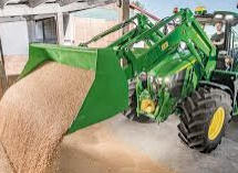 JD LOADERS
 JD MAINTENANCE
 JD INSTRUCTIONS
 JD PROBLEMS
________________________________________________________________________________________
 JD 2025R
 JD 3039R
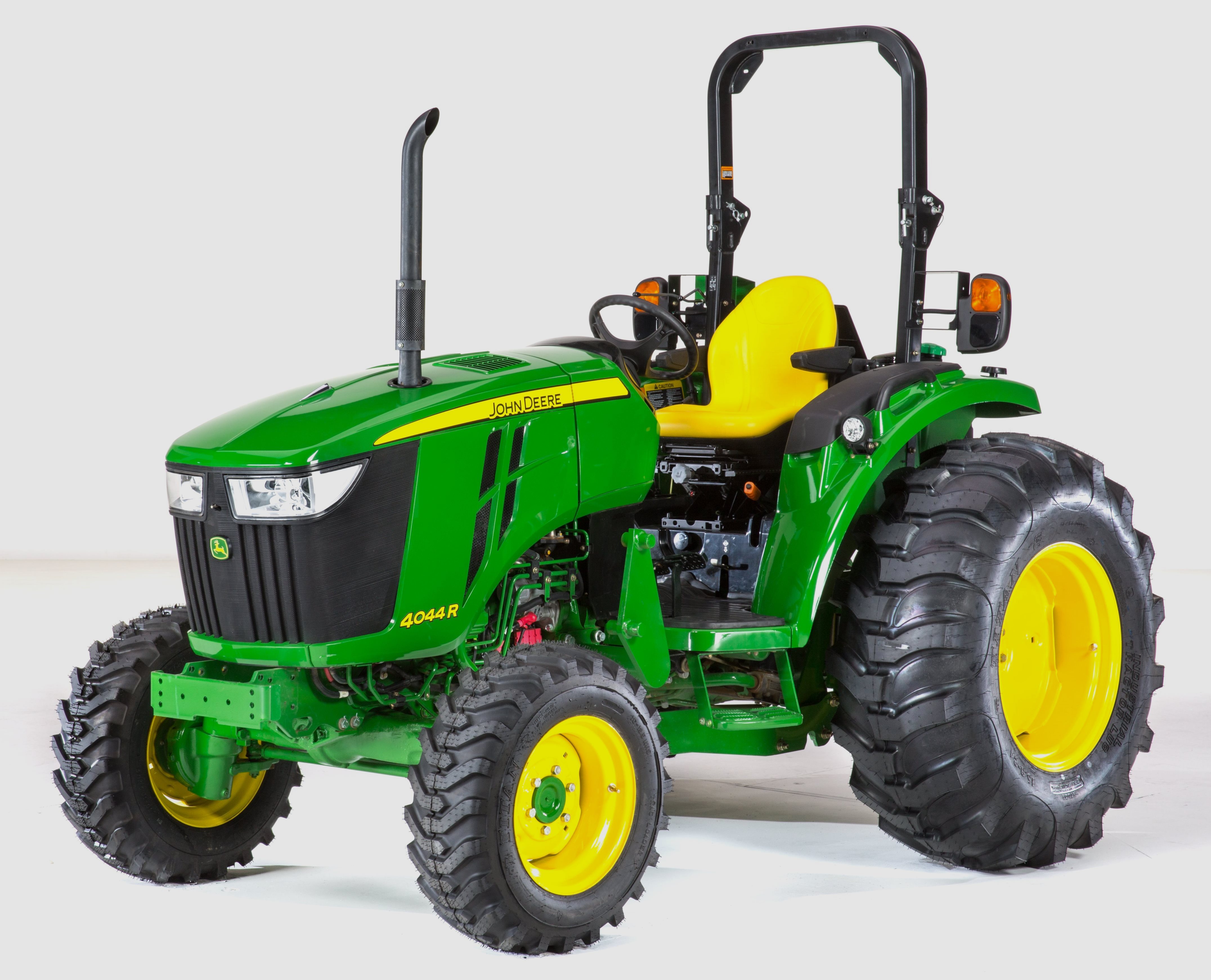 JD 4044R
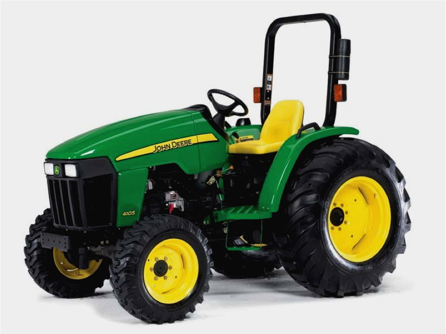 JD 4105
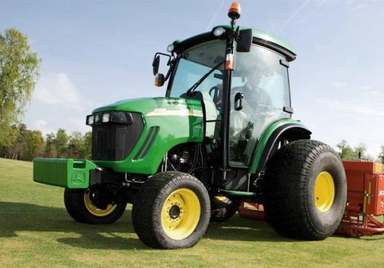 JD 4720
________________________________________________________________________________________
 420 Loader
 419 Loader
 510 Loader
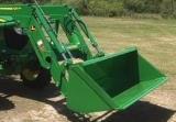 512 Loader
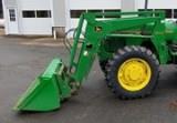 520 Loader
________________________________________________________________________________________
 520M Loader
 540M NSL
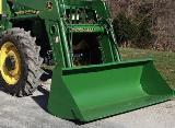 540 Loader
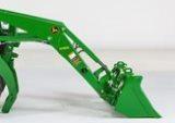 440R Loader
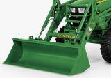 H180 Loader
________________________________________________________________________________________
 JD 5045E
 JD 5085E
 JD 5100M
 JD 6105R
 JD 6120M
________________________________________________________________________________________
 JD 6155M
 JD 6195R
 JD 6210R
 JD 7210R
 JD 7250R
________________________________________________________________________________________
 JD 7310R
 JD 8245R
 JD 8295R
 JD 8370R
 JD 9370R
________________________________________________________________________________________
 120R Loader
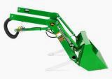 D120 Loader
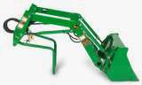 H120 Loader
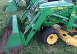 45 Loader
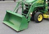 200CX Loader
________________________________________________________________________________________
 D160 Loader
 D170 Loader
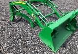 H160 Loader
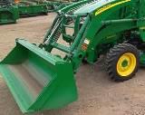 H165 Loader
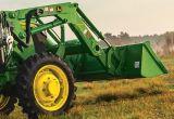 H240 Loader
________________________________________________________________________________________
 210 Loader
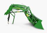 220R Loader
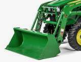 300E Loader
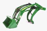 300X Loader
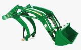 300CX Loader
________________________________________________________________________________________
 JD 9420R
 JD 9510R
 JD GX335
 JD GX85
 JD LA105
________________________________________________________________________________________
 JD 5065M
 JD 5055D
 JD 5115R
 JD 5105M
 JD 6110R
________________________________________________________________________________________
 JD 6130D
 JD 6225
 JD 7530
 JD 4044M
 JD 7185J
________________________________________________________________________________________
 300 Loader
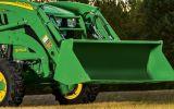 300R Loader
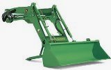 320R Loader
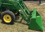 400E Loader
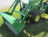 410 Loader
________________________________________________________________________________________
 430 Loader
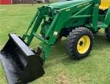 460 Loader
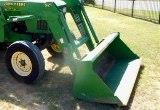 521 Loader
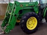 531 Loader
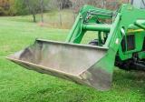 541 Loader
________________________________________________________________________________________
 551 Loader
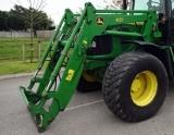 631 Loader
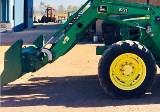 651 Loader
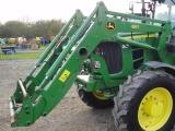 661 Loader
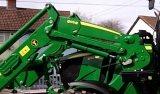 603R Loader
________________________________________________________________________________________
 JD D130
 JD D160
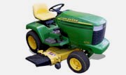 JD 325
 JD 335
 JD 345
________________________________________________________________________________________
 JD 2520
 JD 3005
 JD 3720
 JD 1025R
 JD 3033R
________________________________________________________________________________________
 JD 5090EL
 JD 5100MH
 JD 5075GV
 JD 6090RC
 JD 6110B
________________________________________________________________________________________
 623R Loader
 643R Loader
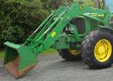 731 Loader
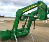 746 Loader
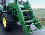 751 Loader
________________________________________________________________________________________
 533 Loader
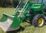 583 Loader
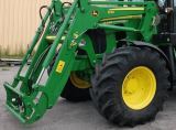 633 Loader
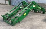 653 Loader
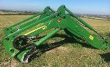 683 Loader
________________________________________________________________________________________
 H260 Loader
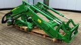 663R Loader
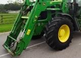 663 Loader
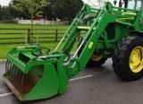 683R Loader
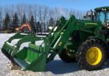 753 Loader
________________________________________________________________________________________
 JD 6125J
 JD 6150RH
 JD 6210J
 JD 7195J
 JD 8310
________________________________________________________________________________________
 JD 6325
 JD 5525
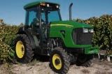 JD 5083EN
 JD 5100GN
 JD 5125R
________________________________________________________________________________________
 210C Backhoe
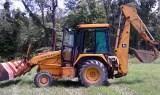 300D Backhoe
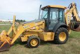 310G Backhoe
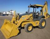 410G Backhoe
 710G Backhoe
________________________________________________________________________________________
 80 Loader
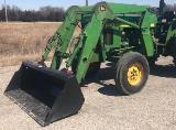 100 Loader
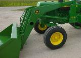 146 Loader
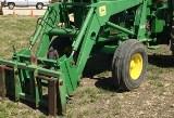 148 Loader
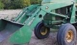 158 Loader
________________________________________________________________________________________
 168 Loader
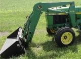 175 Loader
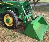 522 Loader
 542 Loader
 540R Loader
________________________________________________________________________________________
 562 Loader
 563 Loader
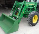 673 Loader
 741 Loader
________________________________________________________________________________________
 L108 Automatic
 L120 Automatic
 LA110 Automatic
 LA120 Automatic
 LA150 Automatic
________________________________________________________________________________________
 LT155
LT155 LT160 Automatic
 LT180 Automatic
 LTR180
 X165
X165________________________________________________________________________________________
 E100
E100 E120
E120 E150
E150 LTR166
________________________________________________________________________________________
 LA135
LA135 LA165
LA165 LX277
LX277 LX288
LX288 LX255
LX255________________________________________________________________________________________
 S240
S240 GT235
GT235 G110 Automatic
 JD 3203
 JD 5520
________________________________________________________________________________________
 JD 316
 JD 420
 JD 425
 JD 445
________________________________________________________________________________________
 JD_5050D
 X300
X300 X304
X304 X310
X310 X110 Automatic
________________________________________________________________________________________
 H310 Loader
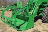 H340 Loader
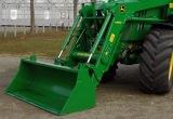 H360 Loader
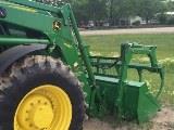 H380 Loader
 H480 Loader
________________________________________________________________________________________
 240 Loader
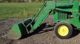 245 Loader
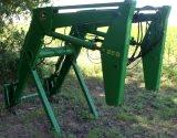 260 Loader
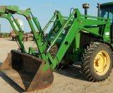 265 Loader
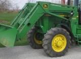 280 Loader
________________________________________________________________________________________
 600R Loader
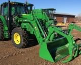 620R Loader
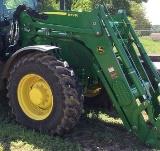 640R Loader
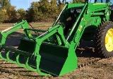 660R Loader
 680R Loader
________________________________________________________________________________________
 JD_5039D
 X146R
X146R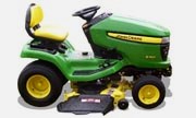 X360
X360 X155R
X155R X140 Automatic
________________________________________________________________________________________
 X350
X350 X380
X380 X500
X500 X590
X590 X700
X700________________________________________________________________________________________
 3036E
3036E 2038R
2038R 3038R
3038R 4049M
4049M JD 4100
________________________________________________________________________________________
 X738
X738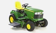 X740
X740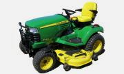 X748
X748 X749
X749 X950R
X950R________________________________________________________________________________________
 JD 4510
 5045D
5045D 5050E
5050E 5060E
5060E 5078E
5078E