________________________________________________________________________________
Tractor Clutch Housing
Clutch Housing for the Tractor Gearbox
(16 forward+8 reverse)
The clutch housing accommodates the drives of the independent PTO,
Hydraulic Lift Linkage pump and a pump of the transmission hydraulic
system.

1 – force-transmission shaft; 2, 9 – PTO driving shaft; 3 – clutch
release shifter support; 4, 7 – collars; 5, 6, 17, 18, 23, 27 –
bearings; 8 – splined bushing; 10 – PTO driven shaft; 11 – bearing; 12 –
packing liner; 13, 15 – covers; 14 – bolt; 19, 26 – pinion-shaft; 20 –
Hydraulic Lift Linkage and transmission pumps drive gear; 21 – spindle;
22 – axle; 24 – check ring; 25 – pinion-shaft; 28 – housing
The driving shaft (2, 9) of the independent PTO drive supported in
bearings (5, 6) has two ring gears. A pinion (16) of the independent PTO
drive is in constant mesh with the smaller ring gear, while a gear (20)
of the pump of the transmission hydraulic system and that of the
Hydraulic Lift Linkage is in mesh with the other ring gear.
The pump of the transmission hydraulic system is driven from the driving
shaft (2, 9) through gears (20, 26, 25).
With the clutch engaged, the torque from the clutch actuator plates is
transmitted to the gearbox primary shaft through the shaft (1) and the
bushing (8).
Clutch Housing for the Tractor Gearbox
(24 forward+12 Reverse)
The tractor clutch housing (30) accommodates the driving and driven
shafts with the pinions fitted on them and drives of the oil pumps of
the Hydraulic Lift Linkage and transmission hydraulic system.
The driving shaft (4) is supported in two bearing assemblies. The shaft
has a ring gear and splines, on which the pinion (5) is seated.
The pinion (5) causes the rotation of the gear (19) of the driven shaft
of the independent PTO drive (18) and gear (8) for driving the oil
pumps.
The power shaft (1) is passed inside the shaft (4) and transmits the
torque from the clutch to the gearbox primary shaft through the splined
bushing (6).
The driven shaft (18) is supported in two bearings (17, 27) in the
housings of the clutch and gearbox.
The driven gears (19) and (24) of the two-speed drive of the independent
PTO are fitted on the shaft in the needle bearings (25).

1 – power shaft; 2 – bracket, 3,10, 14, 17, 25, 27 – bearings; 4 –
driving shaft; 5 – pinion; 6 – splined bushing; 7 – cover; 8 – Hydraulic
Lift Linkage and transmission pumps drive gear; 9, 15 – pinion shaft; 11
– nut; 12 -pinion shaft; 13 – axle; 16 – collar; 18 – driven shaft; 19 –
gear; 20 – fork; 21 – roller; 22 – cover; 23 – toothed coupling; 24 –
gear; 26 – spindle; 28 – roller; 29 – fork; 30 – housing.
The fixed connection of the gears (19, 24) with the shaft is achieved by
means of the toothed coupling (23), with is moved by means of the fork
(20) and shaft (21).
The Hydraulic Lift Linkage is driven by means of the pinion (5) and gear
(8) and the pump of the transmission hydraulic system is driven through
the pinion (5), gear (8) and shafts (15) and (12).
________________________________________________________________________________
 SPECS
 LOADERS
 MAINTENANCE
 PROBLEMS
________________________________________________________________________________________
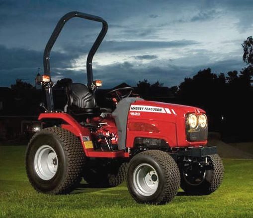 MF 1523
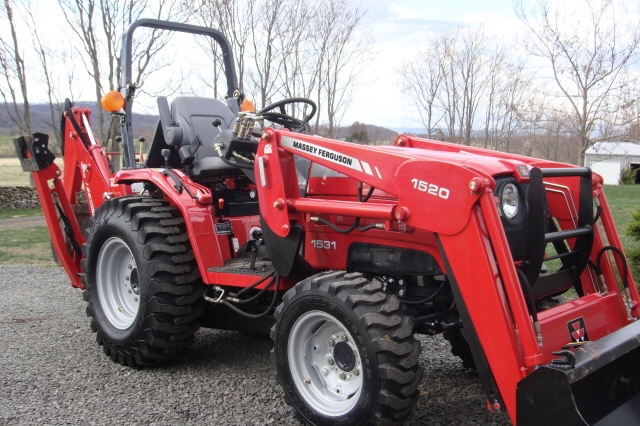 MF 1531
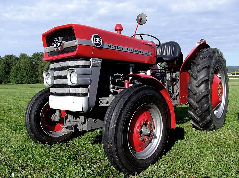 MF 135
 MF 1547
 MF 1635
________________________________________________________________________________________
 231
 231S
 235
 240
 241
________________________________________________________________________________________
_______________________________________________________________________________________
 255
 265
 274
 285
 375
________________________________________________________________________________________
________________________________________________________________________________________
 916X Loader
 921X Loader
 926X Loader
 931X Loader
 936X Loader
________________________________________________________________________________________
 941X Loader
 946X Loader
 951X Loader
 956X Loader
 988 Loader
________________________________________________________________________________________
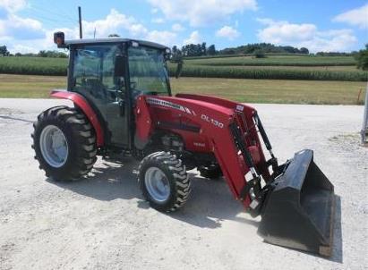 1655
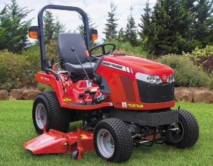 GS1705
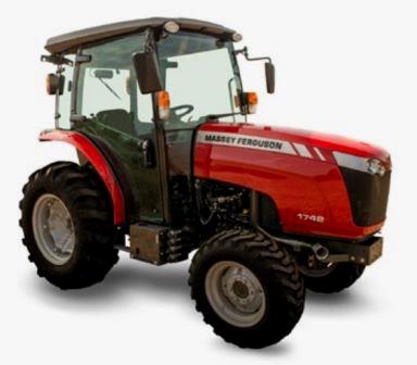 1742
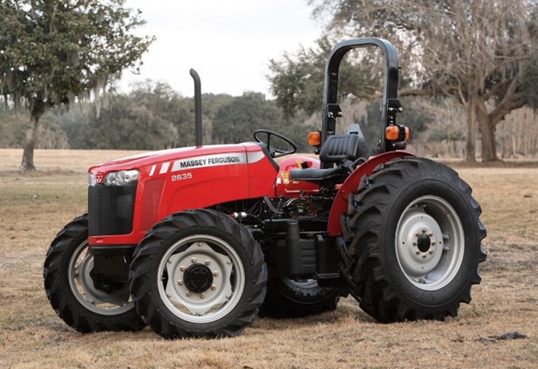 2635
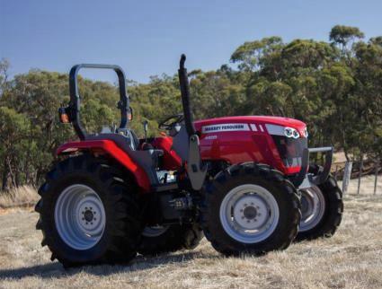 4608
________________________________________________________________________________________
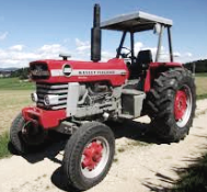 1080
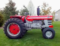 1100
 2615
 3050
 3060
________________________________________________________________________________________
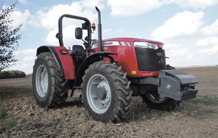 4708
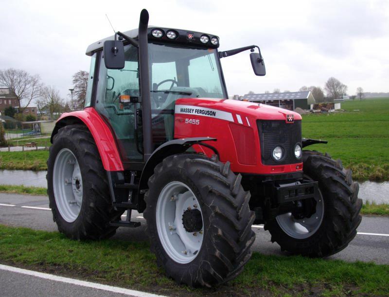 5455
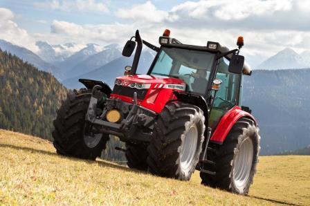 5450
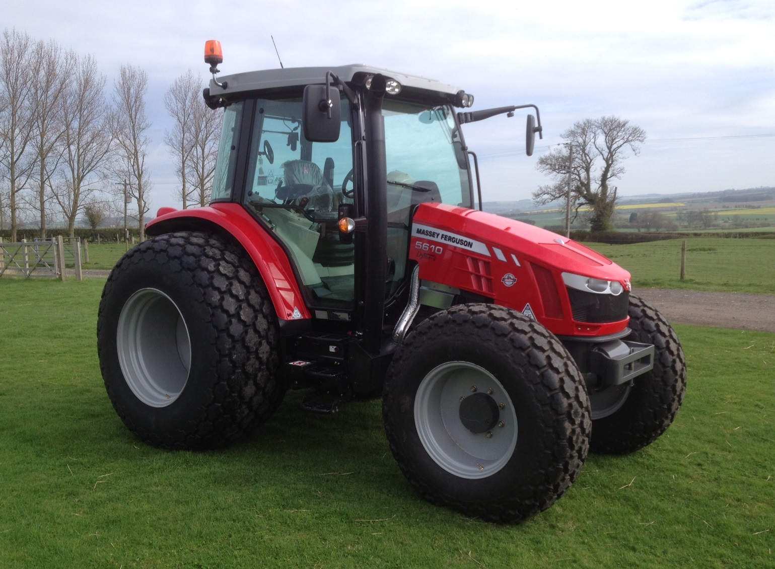 5610
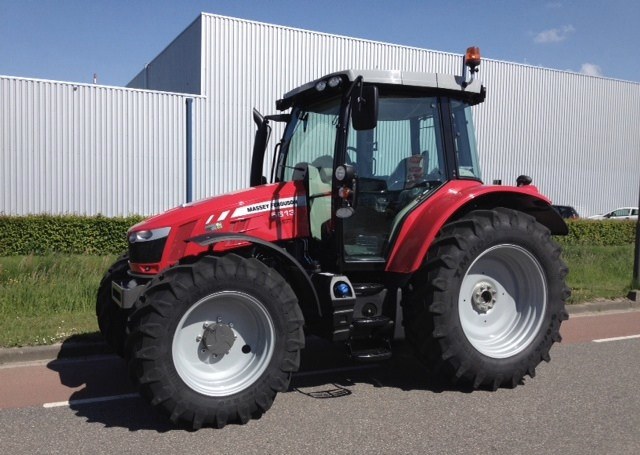 5613
________________________________________________________________________________________
 DL95 Loader
 DL100 Loader
 DL120 Loader
 DL125 Loader
 DL130 Loader
________________________________________________________________________________________
 DL135 Loader
 DL250 Loader
 DL260 Loader
 L90 Loader
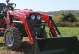 L100 Loader
________________________________________________________________________________________
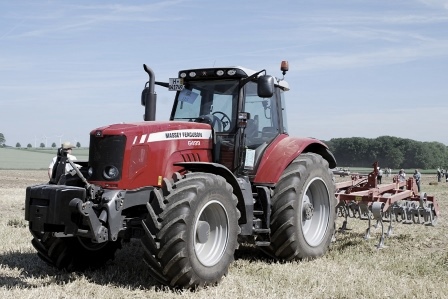 6499
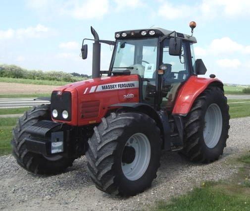 7480
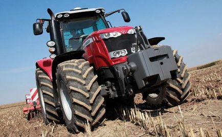 7618
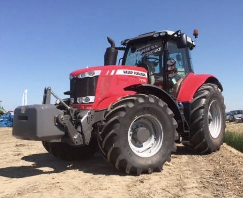 7726
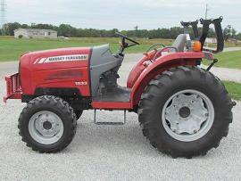 1533
________________________________________________________________________________________
 2604H
 2607H
 4455
 4610M
 4710
________________________________________________________________________________________
 L105E Loader
 L210 Loader
 1014 Loader
 1016 Loader
 1462 Loader
________________________________________________________________________________________
 1525 Loader
 1530 Loader
 232 Loader
 838 Loader
 848 Loader
________________________________________________________________________________________
 5712SL
 6713
 6715S
 7475
 7615
________________________________________________________________________________________
 7716
 7724
 8240
 8650
 8732
________________________________________________________________________________________
 246 Loader
 1036 Loader
 1038 Loader
 1080 Loader
 856 Loader