________________________________________________________________________________
Massey Ferguson 6480 Tractor Removable PTO shaft
On Massey Ferguson 6455, 6465, 6480, 6290 Tractor, the driven pinions
(7) (18) are fitted on the power take-off PTO shaft located on the lower
rear housing. These pinions are constantly engaged with the driving
pinion(s) (depending on version) and driven by the upper shaft line
where the engine speed is transmitted by the power take-off clutch.
At the front, the removable shaft (12) turns on a roller bearing (24)
inserted into a fixed bearing block on the rear of the centre housing.
At the rear, the shaft is supported by a splined sleeve (5) that turns
in taper roller bearings.
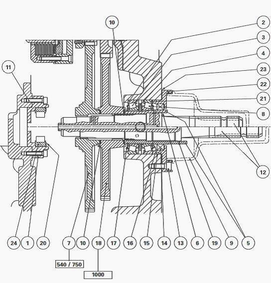
Washer (4) is integral via a tab with sleeve (5) which itself is
integral with shaft (12) via splines. The sleeve is serrated all around
its outside edge and transmits speed information to the onboard
electronic system via the sensor located on the right-hand side of the
rear housing.
An oil splash from the centre housing along
with a central port and radial channels drilled in the shaft provide
lubrication of the:
- friction washers (10)
- taper roller bearings.
In the 540 rpm or 750 rpm (optional) configurations, the shaft (12) is
integral with pinion (7) via splines. Pinion (18) is an idling gear that
runs on the hubs of pinion (7) and sleeve (5). In the 1000 rpm
configuration, the shaft (12) is integral with pinion (18) via splines.
Pinion (7) is an idling gear that runs on the hub of pinion (18) and the
front bearing. The oil tightness of the rear bearing is provided by
cassette seal (14) and O’ring (15). Bearing clearance is adjusted by
shim(s) (23) placed between the rear housing and bearing (22).
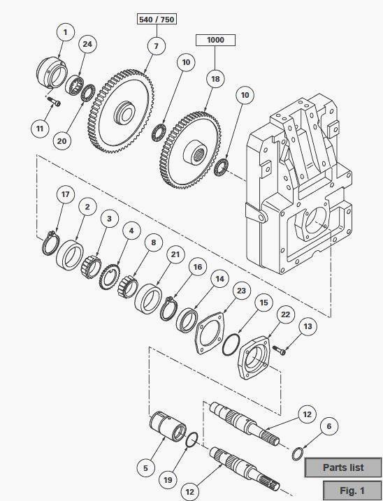
Fig.47. Part list
(1) Front bearing, (2) Bearing cup, (3) Bearing cone, (4) Castellated
washer, (5) Serrated sleeve, (6) Snap ring, (7) 540 or 750 rpm driven
pinion, (8) Bearing cone, (9) Protector, (10) Friction washer, (11)
Bolt, (12) Shaft, (13) Bolt, (14) Cassette seal, (15) O'ring, (16)
Circlip, (17) Circlip, (18) 1000 rpm driven pinion, (19) O'ring, (20)
Friction washer, (21) Bearing cup, (22) Bearing, (23) Shim(s), (24)
Roller bearing
Special point
-- The removal and refitting of the
Massey Ferguson 6455, 6465, 6480, 6290 Tractor power take-off PTO housing is necessary for all maintenance
operations on the layshaft apart from the removal of bearing (22), the
replacement of seals (14) (15) and shaft (12). The centre housing must
be drained either partially or completely depending on the operation and
must be brought up to level again after the maintenance.
Disassembling and reassembling pinions
540 - 1000 rpm or 750 - 1000 rpm
- The 540 - 1000 rpm and 750 - 1000 rpm versions have the same assembly
configuration. The only difference is that the 540 rpm and 750 rpm
pinions have a different number of teeth.
Uncouple the power take-off housing from the centre housing.
Recover the friction washer (20).
Remove snap ring (6) and support driven pinions (7) (18).
Pull shaft (12). Remove the pinions. Recover the friction washer (10).
Clean and check the components. Replace any parts found to be defective.
Check that the oil channels in shaft (12) are not obstructed. Check that
the interior of sleeve (5) is clean and free of burrs. Lubricate and fit
a new O’ring (19).
Assemble driven pinions (7) (18) and friction washers (10) smeared with
miscible grease and placed according to the overall view. Maintain the
pinions inserted and thrust against sleeve (5).
Engage shaft (12) against the shoulder of the sleeve.
Install snap ring (6).
Smear friction washer (20) with miscible grease and apply it against
bearing (24).
Couple the MF 6455, 6465, 6480, 6290 Tractor PTO housing to the centre
housing.
Disassembling and reassembling the
front bearing block (1)
Uncouple the power take-off housing from the centre housing.
Take out bolts (11). Remove the front bearing block (1).
Where necessary, note the manner in which bearing (24) is assembled and
then extract it from the bearing block.
Clean and check the components. Replace any parts found to be defective.
If disassembled, position bearing (24) using an appropriate insertion
drift, with the rounded cage holding the rollers turned to face the
forward end of shaft (12).
Install bearing block (1). Fit and tighten bolts (11) with their threads
lightly smeared with Loctite 241 and tighten to a torque of 27 - 35 Nm.
Couple the power take-off housing to the centre housing.
Disassembling and reassembling the
bearings
Uncouple the power take-off housing from the centre housing.
Take out the bolt from the lower sensor and remove it. Disassemble the
pinions and the shaft (see A).
Take out bolts (13), remove bearing block assembly (22) comprising
sleeve (5), oil seal (14), O’rings (15) (19), shim(s) (23), bearing cup
(21), bearing cones (3) (8) and castellated washer (4).
Take off bearing cup (2).
On sleeve (5), remove circlip (17). Remove bearing cone (3), castellated
washer (4), bearing cone (8) and circlip (16).
Special point
- If the MF 6455, 6465, 6480, 6290 Tractor power take-off housing,
bearing block (22), taper roller bearings (2) (3) (8) (21) or
castellated washer (4) had to be replaced, the bearings must be shimmed
again.
Clean and check the components. Replace any parts found to be defective.
Check that the oil channels in shaft (12) are not obstructed.
On sleeve (5), place circlip (16), bearing cones (3) (8) separated by
castellated washer (4). Fit circlip (17).
Install cup (2), sleeve (5) assembled, cup (21), bearing block (22) with
shim(s) (23, O’rings (15) (19). Install and tighten bolts (13) to a
torque of 72 - 96 Nm.
Install the 540 - 1000 rpm or 750 - 1000 rpm pinions and shaft (12).
Couple the Massey Ferguson 6455, 6465, 6480, 6290 Tractor power take-off PTO to the centre housing.
Install the sensor, O’ring and bolt.
Removing and refitting the shaft and replacing the oil seal.
Partially drain the centre housing in order to avoid oil from running
through the shaft bore, or raise the rear axle of the tractor (after
chocking the front wheels).
Remove O’ring (6). Take out shaft (12). Take off O’ring (19).
Check that the interior of sleeve (5) is clean and free of burrs.
Lubricate and fit a new O’ring.
Check that the channel in the shaft is not obstructed. Clean and then
engage the shaft thrust up against the shoulder on sleeve (5). Install
snap ring (6).
Remove the trolley jack.
Replacing the oil seal on rear bearing block.
Partially drain the centre housing.
Take out bolts (13), remove bearing block (22) while holding the shaft
(12) pushed forwards in order not to displace sleeve (5) on pinion (18).
Take off seal (15). Recover the shim(s) (23).
Note the direction of assembly of seal (14) and then extract it.
Clean and check the components. Replace any parts found to be defective.
If necessary, before fitting seal (14). Lightly smear the external
diameter of seal (14) with Loctite 542. Using a press, insert the
cassette seal into the bearing block (22) with its lip turned to face
taper roller bearing (8) (21).
Screw two diametrically opposed threaded rods (O 10 x 150, length
approximately 50 mm) in place of bolts (13). Check that sleeve (5) is
free from burrs. Lubricate the internal diameter of cassette seal (14)
with transmission oil. Refit the bearing block fitted with lubricated
seal (15) and the shims (23) removed during disassembly.
Hold the shaft (12) pushed forwards, as described in operation 35.
Alternatively and uniformly screw two bolts and washers on the threaded
rods so as to insert the bearing parallel with the face of the housing.
Remove the threaded rods. Fit and tighten the initial bolts (13) to
72-96 Nm.
Top up the oil level in the housings and check it on the transparent
tube mounted on the left-side of the centre housing.
Shimming
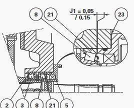
Carry out the shimming of bearings (2) (3) and (8) (21) before fitting
seal (14).
Using a depth gauge, measure dimension A on the MF 6455, 6465, 6480,
6290 Tractor power take-off PTO
housing.
Place the sleeve prepared in operation 24, the bearing cups and bearing
block (22) thrust against a locally manufactured support.
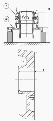
With the help of an operator, apply strong continuous pressure around
the rim of the cup (2). At the same time, alternately turn the sleeve
left and right in order to correctly seat the bearing cones in their
cups. Measure dimension B at two opposing points. Take the average of
the two measurements.
Apply the formula B - A. Place a thickness of shim(s) (23) in order to
provide a clearance of: J1 = 0.05 mm to 0.15 mm.
________________________________________________________________________________
 SPECS
SPECS LOADERS
 MAINTENANCE
 PROBLEMS
________________________________________________________________________________________
 MF 1523
 MF 1531
 MF 135
 MF 1547
 MF 1635
________________________________________________________________________________________
 231
231 231S
231S 235
235 240
240 241
241________________________________________________________________________________________
 255
255 265
265 274
274 285
285 375
375________________________________________________________________________________________
________________________________________________________________________________________
 916X Loader
 921X Loader
 926X Loader
 931X Loader
 936X Loader
________________________________________________________________________________________
 941X Loader
 946X Loader
 951X Loader
 956X Loader
 988 Loader
________________________________________________________________________________________
 1655
1655 GS1705
 1742
1742 2635
2635 4608
4608________________________________________________________________________________________
 1080
1080 1100
1100 2615
2615 3050
3050 3060
3060________________________________________________________________________________________
 4708
4708 5455
5455 5450
5450 5610
5610 5613
5613________________________________________________________________________________________
 DL95 Loader
 DL100 Loader
 DL120 Loader
 DL125 Loader
 DL130 Loader
________________________________________________________________________________________
 DL135 Loader
 DL250 Loader
 DL260 Loader
 L90 Loader
 L100 Loader
________________________________________________________________________________________
 6499
6499 7480
7480 7618
7618 7726
7726 1533
1533________________________________________________________________________________________
 2604H
2604H 2607H
2607H 4455
4455 4610M
4610M 4710
4710________________________________________________________________________________________
 L105E Loader
 L210 Loader
 1014 Loader
 1016 Loader
 1462 Loader
________________________________________________________________________________________
 1525 Loader
 1530 Loader
 232 Loader
 838 Loader
 848 Loader
________________________________________________________________________________________
 5712SL
 6713
6713 6715S
6715S 7475
7475 7615
7615________________________________________________________________________________________
 7716
7716 7724
7724 8240
8240 8650
8650 8732
8732________________________________________________________________________________________
 246 Loader
 1036 Loader
 1038 Loader
 1080 Loader
 856 Loader