________________________________________________________________________________
MF 3050, 3080 Tractor Push-type Clutch hydraulic slave cylinder
Hydraulic slave cylinder assembly
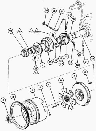
Fig. 1A/2A. Massey Ferguson MF 3060, 3080, 3050 Tractors
Push-type Clutch
Removal:
- Split the Massey Ferguson 3085, 3070 tractor between the engine and
the gearbox.
- Disconnect the bleed pipe and supply pipe from the slave cylinder
assembly.
- To remove the hydraulic slave cylinder assembly complete, do not
separate the bearing carrier fully from the cylinder to gain access to
the attaching bolts.
- Pull the release bearing carrier 40 mm away from the cylinder and
remove the boot (10).
- Using short Allen keys, unscrew the two bolts (12) and bolts (12A).
Refitment:
- Coat the bolts with Loctite 241. Fit and tighten the bolts to a torque
of: 8 diam: 25-35 Nm 10 diam: 40-70 Nm.
- Refit the boot (10). Refit the bleed pipe (24) and supply pipe (21).
- Refit the gearbox to the MF 3065, 3085, 3070 tractor.
- Remove air from the clutch hydraulic control system.
- To avoid damage to the release bearing carrier (9) use plastic
protective jaws and grip the collar lightly.
Slave cylinder seal
Replacement:
- Split the Massey Ferguson 3060, 3070 tractor between the engine and
the gearbox.
- Disconnect the bleed pipe (24) and the supply pipe (21).
- Remove the rubber boot (10).
- Withdraw the push-type clutch release bearing carrier (9) from the
slave cylinder (11).
- Remove the two bolts (12) and the bolt (12A)
- Remove the slave cylinder-guide assembly.
- Separate the slave cylinder and the guide (17).
- Remove the "O" ring (13)
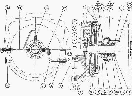
- Remove: the elbow union (22), the straight union (23),
- Remove the rod (18)
- Remove the MF 3060, 3085, 3065 tractor clutch release bearing.
Disassembly
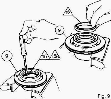
Fig.9
Remove:
- on the release bearing carrier (9): the scraper ring 16, the seal 15
and the "O" ring 15A (Fig.9).
- on the slave cylinder (11): the seal 14 and the "O" ring 14A.
To remove the seals and "O" rings, use a suitably protected screwdriver
(Fig.9). The bores and grooves of the parts must be free from scoring
and damage.
Reassembly of "o" ring 14A and bush 14 in cylinder.
- Clean the cylinder (11).
- Position the cylinder with the groove facing upwards.
- Lubricate and it the "O" ring 14A in the groove. Do not twist it.
- Form the seal 14 into a heart-shape. Important: The lip of the seal
must face outwards.
- Fit the seal 14 into the groove and push it gradually towards the "O"
ring 14AV
- Lubricate the seal and the cylinder bore.
- To ensure seat seated properly, use bearing carrier as a mandrill.
Lubricate the release bearing carrier (9)
- Insert the release bearing carrier (9) in the front of the Massey
Ferguson 3080, 3085, 3065 tractor clutch cylinder (11) using the tool.
- Turn the release bearing carrier approximately one turn in the
cylinder to bed in seal. Remove the release bearing carrier: the seal 14
is now fitted.
- Reassembly of "O" ring 15A and seal 15 on release bearing carrier (9).
- Clean the release bearing carrier.
- Position the release bearing carrier with the groove facing upwards.
- Lubricate and fit the "O" ring 15A in the groove. Do not twist it.
- Form the seal 15 into a heart-shape. Important: The lip of the seal 15
must face outwards.
- Fit the seal 15 into the groove and push it gradually towards the "O"
ring 15AV Note: To ensure seal seated properly, use guide as a mandril.
- Lubricate the seal 15 and the guide (17). Insert the guide (17) into
the front of the release bearing carrier (9) using the tool shown.
- Turn the guide approximately one turn. Remove the guide. The seal 15
is now fitted.
- Using a suitable arrangement to support the bearing carrier, press in
the scraper ring 16.
- Fit the release bearing.
- Lubricate the seal 15Y the seal 16and the release bearing carrier
bore.
- Fit the rod (18) after coating it with Loctite 241. Tighten to &
torque of 25-35 Nm.
- Lubricate the guide (17), the seal (14) and the release bearing
carrier (9).
- Position the "O" ring (13) on the guide.
- Assemble the cylinder (11) with the guide (17).
- Refit the bolts (12) and (12A).
- Press the release bearing carrier (9) into the cylinder (11) so as to
leave a gap of 40 mm to allow access for the Allen keys to tighten bolts
(12) and (12A).
- Screw on the unions (22) and (23).
- Locate the slave cylinder assembly on the Speeds-shift cover.
- Coat the bolts (12) and (12A) with Loctite 241. Using the short Allen
keys, tighten to a torque oL 8 diam. : 25-35 Nm 10 diam. : 40-70 Nm
- Fit the boot (10). Refit the bleed pipe (24) and supply pipe (21).
- Refit the gearbox to the MF 3060, 3080, 3050 tractor.
- Remove air from the clutch hydraulic control system.
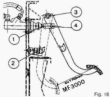
Fig.18
Removing air from the clutch hydraulic system.
Checking piston travel in the slave cylinder.
Clutch pedal adjustment.
Before assembly coat the pins (3) and (4) with molybdenum disulphide
grease.
Coat the threads of the rod (1) (Fig, 18) with Loctite 542. Adjust the
rod to obtain a pedal travel of 170 mm between the disengaged position
(pedal up against the stop (2)) and the engaged position.
________________________________________________________________________________
 SPECS
SPECS LOADERS
 MAINTENANCE
 PROBLEMS
________________________________________________________________________________________
 MF 1523
 MF 1531
 MF 135
 MF 1547
 MF 1635
________________________________________________________________________________________
 231
231 231S
231S 235
235 240
240 241
241________________________________________________________________________________________
 255
255 265
265 274
274 285
285 375
375________________________________________________________________________________________
________________________________________________________________________________________
 916X Loader
 921X Loader
 926X Loader
 931X Loader
 936X Loader
________________________________________________________________________________________
 941X Loader
 946X Loader
 951X Loader
 956X Loader
 988 Loader
________________________________________________________________________________________
 1655
1655 GS1705
 1742
1742 2635
2635 4608
4608________________________________________________________________________________________
 1080
1080 1100
1100 2615
2615 3050
3050 3060
3060________________________________________________________________________________________
 4708
4708 5455
5455 5450
5450 5610
5610 5613
5613________________________________________________________________________________________
 DL95 Loader
 DL100 Loader
 DL120 Loader
 DL125 Loader
 DL130 Loader
________________________________________________________________________________________
 DL135 Loader
 DL250 Loader
 DL260 Loader
 L90 Loader
 L100 Loader
________________________________________________________________________________________
 6499
6499 7480
7480 7618
7618 7726
7726 1533
1533________________________________________________________________________________________
 2604H
2604H 2607H
2607H 4455
4455 4610M
4610M 4710
4710________________________________________________________________________________________
 L105E Loader
 L210 Loader
 1014 Loader
 1016 Loader
 1462 Loader
________________________________________________________________________________________
 1525 Loader
 1530 Loader
 232 Loader
 838 Loader
 848 Loader
________________________________________________________________________________________
 5712SL
 6713
6713 6715S
6715S 7475
7475 7615
7615________________________________________________________________________________________
 7716
7716 7724
7724 8240
8240 8650
8650 8732
8732________________________________________________________________________________________
 246 Loader
 1036 Loader
 1038 Loader
 1080 Loader
 856 Loader