________________________________________________________________________________
Tractor Power Take-off (РТО)
The power take-off housing, fitted to the rear of the centre housing,
houses all mechanical components of the rear power take-off on the
tractors. The power take-off PTO is independent of the transmission.
On tractors fitted with a Heavy gearbox, the input shaft is integral via
splines with the vibration damper fixed to the engine flywheel. It
transmits the engine speed to the power take-off multidisc clutch via a
shaft line comprising two layshafts.
The first layshaft is linked by splines to the engine input shaft and,
at the front, to the hydraulic pump drive pinion. The second layshaft is
splined at the front on the hydraulic pump drive pinion and at the rear
on the power take-off PTO clutch.
On tractors fitted with an AG150 or AG250 Powershift gearboxes, the
engine speed is transmitted to the power take-off clutch by a shaft line
comprising four shafts.
The first shaft is likewise driven via the vibration damper fitted to
the engine flywheel. The second shaft, passing through the gearbox, is
linked to the third shaft by a sleeve and drives the hydraulic pump
drive pinion.
As in the version mentioned above, the last shaft is splined at the
front on the hydraulic pump drive pinion and at the rear on the PTO
clutch.
Types of power take-off (PTO)
available
"a" : with long or short removable shaft - 540 / 1000 rpm or with an
option of 750 / 1000 rpm
"b" : with a jaw coupler and short or long shaft with disc - 540 / 1000
rpm or 750 / 1000 rpm
"c" : with fixed coupler and shaft with disc - 1000 rpm
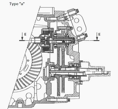
PTO Type "a"
- the clutch unit is integral via splines with a double pinion that is
constantly engaged with the 540 / 1000 rpm or 750 / 1000 rpm pinions
that rotate the 1000 rpm shaft or the 750 rpm shaft at the required
speed.
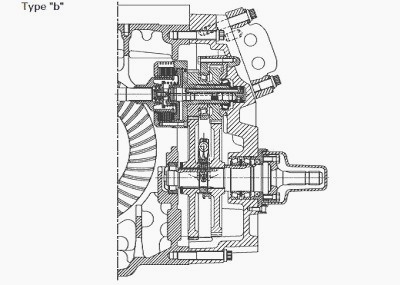
PTO Type "b"
- the clutch unit is integral via splines with two pinions that are
constantly engaged with the 540 / 1000 rpm or 750 / 1000 rpm pinions
that rotate the power take-off РТО output shaft when the coupler is
either moved forwards, to the 540 / 1000 rpm position, or rearwards to
the 1000 rpm position, depending on the speed required.
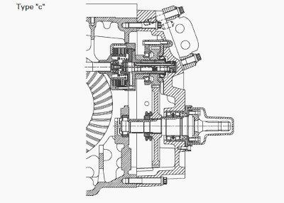
PTO Type "c"
- the clutch unit is integral via splines with a single pinion that is
constantly engaged with the 1000 rpm pinion that rotates the power
take-off PTO output shaft.
- In the type "c", a spacer replaces the 540 or 750 rpm drive pinion.
The coupler is integral via splines with the 1000 rpm drive pinion. It
is held in place by a snap ring located on the hub. This hub is itself
immobilised by another snap ring fitted on the output shaft.
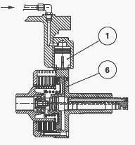
When the clutch is disengaged and the control button in the cab is
placed in the PTO brake position, the 17 bar pressure acts upon piston
(1) and it enters in contact with the outside edge of unit (6) and thus
brakes its rotation.
Construction PTO
The clutch, located on the upper shaftline, is supported by two taper
roller bearings. The bearing cups are fitted in two carriers fixed to
the power take-off PTO housing and the bearing cones are positioned on
two spans inside the clutch housing.
The front bearing cone is force fitted on:
- the clutch unit (PTO type "a")
- the 540 or 750 rpm pinion drive pinion (PTO type "b")
- the spacer (PTO type "c")
The rear bearing cone is mounted free on all types. The bearing
clearance is adjusted by means of shims placed between the two carriers.
The lower shaft line comprises:
- A unit fixed by bolts on the rear of the centre housing, in which a
roller bearing (type "a" PTO) is fitted. On the other types, this
bearing is force fitted, preceded by an oil deflector, in the centre
housing.
- A rear bearing comprising two taper roller bearings; their clearance
is adjusted by shims placed between the power take-off housing and the
bearing.
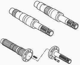
On the type "a" power take-off, the previously stated bearings are
fitted on a sleeve integral with the power take-off output shaft.
- A cassette seal provides oil tightness for the bearing. Depending on
the type of power take-off, the type of tool that is to be driven and
the recommended rotational speed, the output shafts ((removable or with
interchangeable end-piece) may be of different lengths and have 6, 20 or
21 splines.
________________________________________________________________________________
________________________________________________________________________________________
________________________________________________________________________________________
________________________________________________________________________________________
________________________________________________________________________________________
________________________________________________________________________________________
________________________________________________________________________________________
________________________________________________________________________________________
________________________________________________________________________________________
________________________________________________________________________________________
________________________________________________________________________________________
________________________________________________________________________________________
________________________________________________________________________________________
________________________________________________________________________________________
________________________________________________________________________________________
________________________________________________________________________________________
________________________________________________________________________________________
________________________________________________________________________________________
________________________________________________________________________________________
 SPECS
SPECS LOADERS
 MAINTENANCE
 PROBLEMS
 MF 1523
 MF 1531
 MF 135
 MF 1547
 MF 1635
 231
231 231S
231S 235
235 240
240 241
241 255
255 265
265 274
274 285
285 375
375 916X Loader
 921X Loader
 926X Loader
 931X Loader
 936X Loader
 941X Loader
 946X Loader
 951X Loader
 956X Loader
 988 Loader
 1655
1655 GS1705
 1742
1742 2635
2635 4608
4608 1080
1080 1100
1100 2615
2615 3050
3050 3060
3060 4708
4708 5455
5455 5450
5450 5610
5610 5613
5613 DL95 Loader
 DL100 Loader
 DL120 Loader
 DL125 Loader
 DL130 Loader
 DL135 Loader
 DL250 Loader
 DL260 Loader
 L90 Loader
 L100 Loader
 6499
6499 7480
7480 7618
7618 7726
7726 1533
1533 2604H
2604H 2607H
2607H 4455
4455 4610M
4610M 4710
4710 L105E Loader
 L210 Loader
 1014 Loader
 1016 Loader
 1462 Loader
 1525 Loader
 1530 Loader
 232 Loader
 838 Loader
 848 Loader
 5712SL
 6713
6713 6715S
6715S 7475
7475 7615
7615 7716
7716 7724
7724 8240
8240 8650
8650 8732
8732 246 Loader
 1036 Loader
 1038 Loader
 1080 Loader
 856 Loader