
________________________________________________________________________________
Massey Ferguson 5470, 5475 Tractor ground Power take off 4WD version
Massey Ferguson 5470, 5475
Tractors may be fitted with ground PTO. Unlike the independent PTO
system where the PTO speed depends on the engine speed, the proportional
PTO is driven by the rear differential pinion and the PTO shaft speed is
proportional to the travel speed of the tractor.
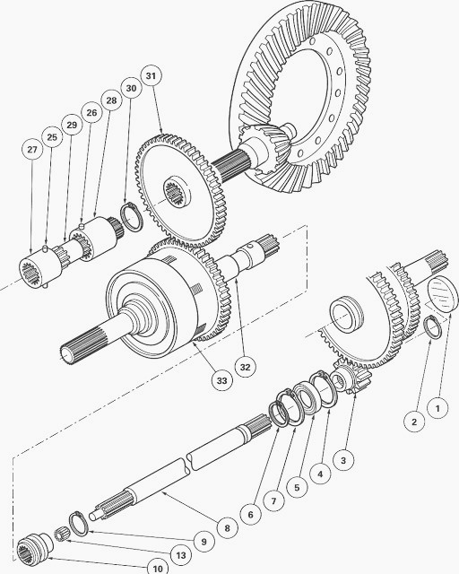
The pinion comprises a gear (31) constantly meshed with the bell gear
(33) (4WD). The sliding gear (10) secures the shaft (8) in rotation with
the shaft (32) (4WD). The gear (3) fitted at the end of the shaft (8)
drives the 540 rpm gear on the rear PTO line.
The movement of the sliding gear (10) is obtained by a pad hinged on a
pin fitted on the left in the lower part of the rear axle housing and
controlled by a rod and a cable operated by a lever in the cab.
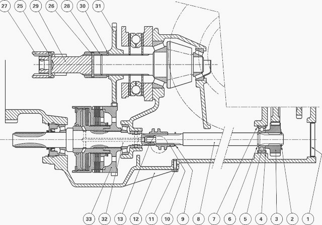
Fig.67. Parts list MF 5470, 5475 4WD
(01) Plug, (02) Circlip, (03) Gear, (04) Circlip, (05) Bearing, (06)
Circlip, (07) Circlip, (08) Shaft, (09) Circlip, (10) Sliding gear, (11)
Screw, (12) Cover plate, (13) Needle roller bearing, (25) Double pin,
(26) Double pin, (27) Sleeve, (28) Sleeve, (29) Shaft, (30) Circlip,
(31) Gear, (32) 4WD shaft, (33) Bell gear
Disassembling the Massey Ferguson
5470, 5475 tractor ground PTO (4WD
version)
Remove the guard, the 4WD shaft and the lubrication pipe from the engine
clutch or Power Shuttle.
Remove the shaft (8). If maintenance is required on the 4WD clutch
assembly, the cones and cups, the shaft and the needle roller bearing,
see chapter 8. If the gear (31) is removed, it is necessary to remove
the right-hand hydraulic cover plate.
Raise the tractor using a jack. Place an axle stand in position. Remove
the wheel.
Tractors with no creeper unit
Drive out the double pins (25) (26) from the coupling sleeves (27) (28).
Slide the sleeves towards each other on the shaft (29).
Remove the assembly (shaft and sleeves).
Take off the circlip (30) and remove the gear (31).
Tractors with a creeper unit
Remove the fork, the sleeve assembly, the connecting shaft and the
coupler.
Take off the circlip (30) and remove the gear (31).
Reassembling the MF 5470, 5475 tractor ground PTO (4WD
version)
Check and clean the components. Replace any defective parts.
If carrying out an operation on the
gear (31)
Tractors with a creeper unit
Install the gear (31). Refit the circlip (30).
Install the fork, the sleeve assembly, the connecting shaft and the
coupler. Fit the sleeve (28) with the long offset between the pin and
the 4WD gear. Replace the pins. Adjust the fork.
Massey Ferguson 5470, 5475 Tractors with no creeper unit
Install the gear (31). Refit the circlip (30).
Install the assembly (connecting shaft and sleeves) then position the
coupling sleeves (27) (28) on the shaft (29).
Install two new double pins (25) (26) on the coupling sleeves. Fit the
sleeve (28) with the long offset between the pin and the 4WD gear. The
long double pin is fitted on the sleeve (27).
MF 5470, 5475 Tractors with or without creeper unit
Install the right-hand hydraulic cover plate. If you have disassembled
the 4WD clutch assembly, the cones and cups, the shaft and the needle
roller bearing.
Place the sliding gear (10) on the shaft (32). Turn the small shoulder E
towards the shaft (32). Install shaft (8).
Top up the rear axle oil level. Refit the hitch hook. Check the correct
operation of the proportional PTO.
Check tightness:
- of the mating face of the cover plate underneath the rear axle
housing.
- the right-hand hydraulic cover plate (if removed).
- Hydraulic unions
Assembling and adjusting the Control
Place lever in the proportional PTO position (clutch engaged).
Screw the clevis (1) level with the end of the threaded part of the
cable (6).
Install the clevis (1) onto lever L with the clip (7). Tighten the nut
(2).
Adjust the sheath end (5) so that the nut (3) is level with the end of
the threaded part.
Tighten nut (4), ensuring that the cable is not pinched.
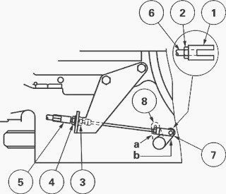
Place the rod (8) in the "engaged" position "a" and ensure that it is
correctly locked.
Screw the clevis (1) level with the threaded
part of the cable (6)
Install the clevis (1) to the rod (8) using the clip (7). Tighten the
nut (2).
Adjust the sheath end (5) using the nut (4) while ensuring that the rod
(8) is still locked in position "a".
Tighten the nut (3). Check the correct operation of the control in the
"disengaged" position "b" and check that the cable is not pinched in any
way when in position "a".
Check for correct operation of the instrument panel indicator light.
________________________________________________________________________________
________________________________________________________________________________________
 SPECS
SPECS LOADERS
 MAINTENANCE
 PROBLEMS
________________________________________________________________________________________
 MF 1523
 MF 1531
 MF 135
 MF 1547
 MF 1635
________________________________________________________________________________________
________________________________________________________________________________________
 231
231 231S
231S 235
235 240
240 241
241________________________________________________________________________________________
 255
255 265
265 274
274 285
285 375
375________________________________________________________________________________________
________________________________________________________________________________________
 916X Loader
 921X Loader
 926X Loader
 931X Loader
 936X Loader
________________________________________________________________________________________
 941X Loader
 946X Loader
 951X Loader
 956X Loader
 988 Loader
________________________________________________________________________________________
 1655
1655 GS1705
 1742
1742 2635
2635 4608
4608________________________________________________________________________________________
 1080
1080 1100
1100 2615
2615 3050
3050 3060
3060________________________________________________________________________________________
 4708
4708 5455
5455 5450
5450 5610
5610 5613
5613________________________________________________________________________________________
 DL95 Loader
 DL100 Loader
 DL120 Loader
 DL125 Loader
 DL130 Loader
________________________________________________________________________________________
 DL135 Loader
 DL250 Loader
 DL260 Loader
 L90 Loader
 L100 Loader
________________________________________________________________________________________
 6499
6499 7480
7480 7618
7618 7726
7726 1533
1533________________________________________________________________________________________
 2604H
2604H 2607H
2607H 4455
4455 4610M
4610M 4710
4710________________________________________________________________________________________
 L105E Loader
 L210 Loader
 1014 Loader
 1016 Loader
 1462 Loader
________________________________________________________________________________________
 1525 Loader
 1530 Loader
 232 Loader
 838 Loader
 848 Loader
________________________________________________________________________________________
 5712SL
 6713
6713 6715S
6715S 7475
7475 7615
7615________________________________________________________________________________________
 7716
7716 7724
7724 8240
8240 8650
8650 8732
8732________________________________________________________________________________________
 246 Loader
 1036 Loader
 1038 Loader
 1080 Loader
 856 Loader