
________________________________________________________________________________
1106 Perkins - Air Inlet and Exhaust System
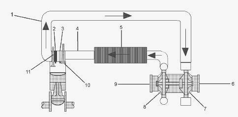
Air inlet and exhaust system - (1) Exhaust manifold (2) Electronic unit
injector (3) Glow plug (4) Inlet manifold (5) Aftercooler core (6)
Exhaust outlet (7) Turbine side of turbocharger (8) Compressor side of
turbocharger (9) Air inlet from the air cleaner (10) Inlet valve (11)
Exhaust valve
The 1106 Perkins diesel engine components of the air inlet and exhaust
system control the quality of air and the amount of air that is
available for combustion. The air inlet and exhaust system consists of
the following components: Air cleaner, Turbocharger, Aftercooler, Inlet
manifold, Cylinder head, injectors and glow plugs, Valves and valve
system components, Piston and cylinder, Exhaust manifold.
Air is drawn in through the air cleaner into the air inlet of the
turbocharger (9) by the turbocharger compressor wheel (8). The air is
compressed and heated to about 150C (300F) before the air is forced to
the after cooler (5). As the air flows through the aftercooler the
temperature of the compressed air lowers to about 50C (120F). Cooling of
the inlet air increases combustion efficiency. Increased combustion
efficiency helps achieve the following benefits: Lower fuel consumption,
Increased horsepower output, Reduced particulate emission.
From the aftercooler, air is forced into the inlet manifold (4). Air
flow from the inlet manifold to the cylinders is controlled by inlet
valves (10). There are two inlet valves and two exhaust valves for each
cylinder. The inlet valves open when the piston moves down on the intake
stroke. When the inlet valves open, cooled compressed air from the inlet
port is forced into the cylinder.
The complete cycle consists of four strokes - Inlet, Compression, Power,
Exhaust. On the compression stroke, the piston moves back up the
cylinder and the inlet valves (10) close. The cool compressed air is
compressed further. This additional compression generates more heat.
If the cold starting system is operating, the glow plugs (3) will also
heat the air in the cylinder. Just before the piston reaches the TC
position, the ECM operates the electronic unit injector. Fuel is
injected into the cylinder. The air/fuel mixture ignites. The ignition
of the gases initiates the power stroke. Both the inlet and the exhaust
valves are closed and the expanding gases force the piston downward
toward the bottom center (BC) position. From the BC position, the piston
moves upward.
This initiates the exhaust stroke. The exhaust valves open. The exhaust
gases are forced through the open exhaust valves into the exhaust
manifold. Exhaust gases from exhaust manifold (1) enter the turbine side
of the turbocharger in order to turn turbocharger turbine wheel (7). The
turbine wheel is connected to the shaft that drives the compressor
wheel. Exhaust gases from the turbocharger pass through exhaust outlet
(6), a silencer and an exhaust pipe.
Valve System Components
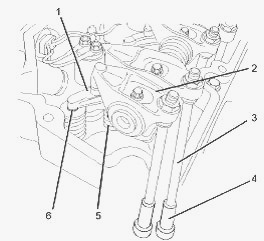
Valve system components - (1) Bridge (2) Rocker arm (3) Pushrod
(4) Lifter (5) Spring (6) Valve
The valve system components control the flow of inlet air into the
cylinders during 1106 Perkins engine operation. The valve system
components also control the flow of exhaust gases out of the cylinders
during engine operation. The crankshaft gear drives the camshaft gear
through an idler gear.
The camshaft must be timed to the crankshaft in order to get the correct
relation between the piston movement and the valve movement. The
camshaft has two camshaft lobes for each cylinder. The lobes operate
either a pair of inlet valves or a pair of exhaust valves. As the
camshaft turns, lobes on the camshaft cause the lifter (4) to move the
pushrod (3) up and down.
Upward movement of the pushrod against rocker arm (2) results in a
downward movement that acts on the valve bridge (1). This action opens a
pair of valves (6) which compresses the valve springs (5). When the
camshaft has rotated to the peak of the lobe, the valves are fully open.
When the camshaft rotates further, the two valve springs (5) under
compression start to expand. The valve stems are under tension of the
springs.
The stems are pushed upward in order to maintain contact with the valve
bridge (1). The continued rotation of the camshaft causes the rocker arm
(2), the pushrods (3) and the lifters (4) to move downward until the
lifter reaches the bottom of the lobe. The valves (6) are now closed.
The cycle is repeated for all the valves on each cylinder.
________________________________________________________________________________
________________________________________________________________________________________
 SPECS
SPECS LOADERS
 MAINTENANCE
 PROBLEMS
________________________________________________________________________________________
 MF 1523
 MF 1531
 MF 135
 MF 1547
 MF 1635
________________________________________________________________________________________
________________________________________________________________________________________
 231
231 231S
231S 235
235 240
240 241
241________________________________________________________________________________________
 255
255 265
265 274
274 285
285 375
375________________________________________________________________________________________
________________________________________________________________________________________
 916X Loader
 921X Loader
 926X Loader
 931X Loader
 936X Loader
________________________________________________________________________________________
 941X Loader
 946X Loader
 951X Loader
 956X Loader
 988 Loader
________________________________________________________________________________________
 1655
1655 GS1705
 1742
1742 2635
2635 4608
4608________________________________________________________________________________________
 1080
1080 1100
1100 2615
2615 3050
3050 3060
3060________________________________________________________________________________________
 4708
4708 5455
5455 5450
5450 5610
5610 5613
5613________________________________________________________________________________________
 DL95 Loader
 DL100 Loader
 DL120 Loader
 DL125 Loader
 DL130 Loader
________________________________________________________________________________________
 DL135 Loader
 DL250 Loader
 DL260 Loader
 L90 Loader
 L100 Loader
________________________________________________________________________________________
 6499
6499 7480
7480 7618
7618 7726
7726 1533
1533________________________________________________________________________________________
 2604H
2604H 2607H
2607H 4455
4455 4610M
4610M 4710
4710________________________________________________________________________________________
 L105E Loader
 L210 Loader
 1014 Loader
 1016 Loader
 1462 Loader
________________________________________________________________________________________
 1525 Loader
 1530 Loader
 232 Loader
 838 Loader
 848 Loader
________________________________________________________________________________________
 5712SL
 6713
6713 6715S
6715S 7475
7475 7615
7615________________________________________________________________________________________
 7716
7716 7724
7724 8240
8240 8650
8650 8732
8732________________________________________________________________________________________
 246 Loader
 1036 Loader
 1038 Loader
 1080 Loader
 856 Loader