
________________________________________________________________________________
1106 Perkins motor - Cylinder Head (Remove and Install)
Removal Procedure
If necessary, remove the secondary fuel filter and the fuel filter base.
If necessary, remove the fuel priming pump and the primary fuel filter. Remove:
- the exhaust manifold.
- the fuel manifold.
- the electronic control module and the mounting bracket.
- the electronic unit injectors.
- the valve mechanism cover base.
- the glow plugs. Drain the coolant from the cooling system into a
suitable container for storage or for disposal.
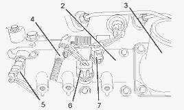
Disconnect the upper radiator hose (not shown) from the water
temperature regulator housing (1) on the cylinder head. Remove the air
inlet hose (not shown) from the inlet connection (3) on the inlet
manifold (2). Follow Steps to disconnect the harness assembly (4) from
the coolant temperature sensor (5). Slide the locking tab (not shown)
into the unlocked position. Disconnect the harness assembly (4) from the
coolant temperature sensor (5).
Follow Steps to disconnect the harness assembly (4) from the boost
pressure sensor (6). Slide the locking tab (not shown) into the unlocked
position. Disconnect the harness assembly (4) from the boost pressure
sensor (6). Follow Steps to disconnect the harness assembly (4) from
inlet air temperature sensor (7).
Slide the locking tab (not shown) into the unlocked position. Disconnect
the harness assembly (4) from the inlet air temperature sensor (7).
Remove all cable ties that secure the harness assembly (4) to the
cylinder head or to the inlet manifold. The harness assembly should be
positioned in order to avoid causing an obstruction during the removal
of the cylinder head.
Loosen the tube clips for the tube assembly (8). Remove the tube
assembly (8) for the fuel return from the cylinder head and from the
transfer pump (not shown). Plug the port in the transfer pump with a new
plug. Cap the tube assembly with new caps. If the 1106 Perkins diesel
engine has a wastegate solenoid, loosen the tube clips for the tube
assembly (9). Remove the tube assembly (9) from the wastegate solenoid
(not shown) and from the cylinder head. Plug the port in the wastegate
solenoid with a new plug. Cap the tube assembly with new caps.
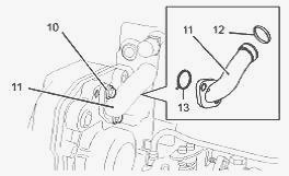
Remove the two setscrews (10). Remove the bypass tube (11) from the
cylinder head. Remove the O-ring seals (12) and (13) from the bypass
tube (11). Discard the O-ring seals.
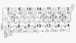
Sequence for tightening the setscrews for the cylinder head - Gradually
loosen the setscrews (14) in the reverse numerical order to the
tightening sequence. Refer to the illustration. Follow the correct
sequence in order to help prevent distortion of the cylinder head.
Remove the setscrews (14) from the cylinder head (15).
Attach a suitable lifting device (16) to the cylinder head (15). Support
the weight of the cylinder head. The weight of the cylinder head is
approximately 66 kg (145.5 lb). A spreader bar must be used in order to
distribute the weight of the cylinder head during the lifting operation.
Use the suitable lifting device (16) to carefully lift the cylinder head
(15) off the cylinder block. Do not use a lever to separate the cylinder
head from the cylinder block. Take care not to damage the machined
surfaces of the cylinder head during the removal procedure.
Remove the cylinder head gasket (17). Discard the cylinder head gasket.
Note the position of the dowels (18) in the cylinder block. If
necessary, remove the water temperature regulator (1) from the cylinder
head (15). If necessary, remove the inlet manifold (2) from the cylinder
head (15).
Installation Procedure
Thoroughly clean the mating surfaces of the 1106 Perkins cylinder head
and the cylinder block. Do not damage the mating surfaces of the
cylinder head of the cylinder block. Ensure that no debris enters the
cylinder bores, the coolant passages, or the lubricant passages. Inspect
the mating surface of the cylinder head for distortion. If the mating
surface of the cylinder head is distorted beyond maximum permitted
limits, replace the cylinder head. If necessary, install the inlet
manifold to the cylinder head.
Inspect the dowels (18) for damage. If necessary, replace the dowels in
the cylinder block. Install Tooling to the cylinder block. Align the
cylinder head gasket (17) with the dowels (18). Install the cylinder
head gasket (17) onto the cylinder block.
Use a suitable lifting device (16) to lift the cylinder head (15). The
weight of the cylinder head is approximately 66 kg (145.5 lb). A
spreader bar must be used in order to distribute the weight of the
cylinder head during the lifting operation. Use Tooling to align the
cylinder head with the cylinder block. Install the cylinder head to the
cylinder block. Ensure that the cylinder head is correctly positioned on
the dowels (18). Remove Tooling.
Clean the setscrews (14). Follow Steps for the procedure to inspect the
setscrews. Check the length of the setscrews. Some diesel engines have
all setscrews of the same length. Some engines have two longer
setscrews. Use a straight edge to check the threads of the setscrews.
Refer to Illustration. Replace any setscrews that show visual reduction
in the diameter of the thread over length (Y). Lubricate the threads and
the shoulder of the setscrews (14) with clean engine oil.
Sequence for tightening the setscrews for the cylinder head - Install
the setscrews (14) to the cylinder head (16). If the 1106 Perkins motor
has two longer setscrews, install the longer setscrews in holes (X).
Tighten the setscrews to a torque of 50 Nm (37 lb ft) in the numerical
sequence. Tighten the setscrews to a torque of 100 Nm (74 lb ft) in the
numerical sequence. Refer to Illustration. Turn the setscrews through an
additional 225 degrees in the numerical sequence. Refer to Illustration.
Use Tooling to achieve the correct final torque.
Use Tooling in order to lubricate the O-ring seals. Install two new
O-ring seals (12) and (13) to the bypass tube (11). Install the bypass
tube in the cylinder head. Install the setscrews (10). Tighten the
setscrews to a torque of 22 Nm (16 lb ft).
Remove the plugs and caps from the ports and tube assemblies. Install
the tube assembly (8) for the fuel return to the cylinder head and to
the transfer pump. Secure the tube clips for the tube assembly (8). If
the diesel engine has a wastegate solenoid, install the tube assembly
(9) for the wastegate solenoid to the cylinder head. Secure the tube
clips for the tube assembly (9).
Follow Steps to connect the harness assembly (4) to the inlet air
temperature sensor (7). Connect the harness assembly (4) to the inlet
air temperature sensor (7). Slide the locking tab (not shown) into the
locked position. Follow Steps to connect the harness assembly (4) to the
boost pressure sensor (6). Connect the harness assembly (4) to the boost
pressure sensor (6). Slide the locking tab (not shown) into the locked
position. Follow Steps to connect the harness assembly (4) to the
coolant temperature sensor (5).
Connect the harness assembly (4) to the coolant temperature sensor (5).
Slide the locking tab (not shown) into the locked position. Use new
cable ties in order to secure the harness assembly to the cylinder head
and to the inlet manifold. Ensure that the harness assembly is not
strained. Ensure that the harness assembly is clear of other engine
components. Install the inlet hose (not shown) to the inlet connection
(3) on the inlet manifold (2).
If necessary, install the water temperature regulator housing (1) to the
cylinder head. Connect the upper radiator hose (not shown) to the water
temperature regulator housing (1) on the cylinder head. Fill the cooling
system with coolant. If necessary, fill the engine oil pan to the
correct level that is indicated on the engine oil level gauge.
Install:
- the glow plugs.
- the valve mechanism cover base.
- the electronic unit injectors.
- the electronic control module and the mounting bracket.
- the fuel manifold.
- the exhaust manifold.
- If necessary, install the fuel filter base and the secondary fuel
filter
- If necessary, install the fuel priming pump and the primary fuel
filter.
________________________________________________________________________________
________________________________________________________________________________________
 SPECS
SPECS LOADERS
 MAINTENANCE
 PROBLEMS
________________________________________________________________________________________
 MF 1523
 MF 1531
 MF 135
 MF 1547
 MF 1635
________________________________________________________________________________________
________________________________________________________________________________________
 231
231 231S
231S 235
235 240
240 241
241________________________________________________________________________________________
 255
255 265
265 274
274 285
285 375
375________________________________________________________________________________________
________________________________________________________________________________________
 916X Loader
 921X Loader
 926X Loader
 931X Loader
 936X Loader
________________________________________________________________________________________
 941X Loader
 946X Loader
 951X Loader
 956X Loader
 988 Loader
________________________________________________________________________________________
 1655
1655 GS1705
 1742
1742 2635
2635 4608
4608________________________________________________________________________________________
 1080
1080 1100
1100 2615
2615 3050
3050 3060
3060________________________________________________________________________________________
 4708
4708 5455
5455 5450
5450 5610
5610 5613
5613________________________________________________________________________________________
 DL95 Loader
 DL100 Loader
 DL120 Loader
 DL125 Loader
 DL130 Loader
________________________________________________________________________________________
 DL135 Loader
 DL250 Loader
 DL260 Loader
 L90 Loader
 L100 Loader
________________________________________________________________________________________
 6499
6499 7480
7480 7618
7618 7726
7726 1533
1533________________________________________________________________________________________
 2604H
2604H 2607H
2607H 4455
4455 4610M
4610M 4710
4710________________________________________________________________________________________
 L105E Loader
 L210 Loader
 1014 Loader
 1016 Loader
 1462 Loader
________________________________________________________________________________________
 1525 Loader
 1530 Loader
 232 Loader
 838 Loader
 848 Loader
________________________________________________________________________________________
 5712SL
 6713
6713 6715S
6715S 7475
7475 7615
7615________________________________________________________________________________________
 7716
7716 7724
7724 8240
8240 8650
8650 8732
8732________________________________________________________________________________________
 246 Loader
 1036 Loader
 1038 Loader
 1080 Loader
 856 Loader