
________________________________________________________________________________
1106 Perkins - Electronic Control Module
The 1106 Perkins engine equipped by Electronic Control Module (ECM) (1)
with functions as a governor and a computer for the fuel system. The ECM
receives signals from the sensors in order to control the timing and the
engine speed. The electronic system consists of the Electronic Control
Module (ECM), the engine sensors and inputs from the parent machine. The
ECM is the computer. The personality module is the software for the
computer. The personality module contains the operating maps.
The operating maps define the following characteristics of the engine:
power, torque curves, speed (rpm), noise, smoke and emissions. The
factory passwords restrict changes to authorized personnel. Factory
passwords are required to clear any event code. The Electronic Control
Module (ECM) has an excellent record of reliability. Any problems in the
system are most likely to be the connectors and the wiring harness. The
ECM should be the last item in troubleshooting the engine. The
personality module contains the software with all the fuel setting
information. The information determines the engine performance. The
personality module is installed behind the access panel on the ECM.
Flash programming is the method of programming or updating the
personality module.
Engine Speed Governor - The electronic controls determine the injection
timing, the amount of fuel that is delivered to the cylinders and the
intake manifold pressure if an electronically controlled wastegate is
installed on the turbocharger. These decisions are based on the actual
conditions and the desired conditions at any given time. The governor
has software that compares the desired engine speed to the actual engine
speed. The actual engine speed is determined through the primary
speed/timing sensor and the secondary speed/timing sensor. If the
desired engine speed is greater than the actual engine speed, the
governor injects more fuel in order to increase engine speed.
Timing Considerations - Once the governor has determined the amount of
fuel that is required, the software must determine the timing of the
fuel injection. Fuel injection timing is determined by the ECM after
considering input from the following components: Engine coolant
temperature sensor, The sensor for the intake manifold air temperature,
The sensor for the intake manifold pressure. At start-up, the ECM
determines the top center position of the number 1 cylinder from the
secondary speed/timing sensor in the fuel injection pump. The Electronic
Control Module (ECM) decides when fuel injection should occur relative
to the top center position.
The ECM optimizes engine performance by control of each of the
electronic unit injectors so that the required amount of fuel is
injected at the precise point of the engine’s cycle. The electronic unit
injectors are supplied high pressure fuel from the fuel injection pump.
The ECM also provides the signal to the solenoid in the fuel injection
pump. The solenoid in the fuel injection pump controls a valve in the
fuel injection pump. This valve controls the pressure in the fuel
injection pump. Fuel that is not required for the 1106 Perkins engine is
diverted away from the fuel injection pump back to the fuel tank. The
ECM adjusts injection timing and fuel pressure for the best engine
performance, the best fuel economy and the best control of exhaust
emissions. The actual timing can be viewed with an electronic service
tool. Also, the desired timing can be viewed with an electronic service
tool.
Fuel Injection - The personality module inside the ECM sets certain
limits on the amount of fuel that can be injected. The FRC Limit is a
limit that is based on intake manifold air pressure and engine rpm. The
FRC Limit is used to control the air/fuel ratio in order to control the
engine’s exhaust emissions. When the ECM senses a higher intake manifold
air pressure, the ECM increases the FRC Limit.
A higher intake manifold air pressure indicates that there is more air
in the cylinder. When the ECM increases the FRC Limit, the ECM allows
more fuel into the cylinder. The Rated Fuel Limit is a limit that is
based on the power rating of the engine and on the engine rpm. The Rated
Fuel Limit enables the engine power and torque outputs to conform to the
power and torque curves of a specific engine model. These limits are in
the personality module and these limits cannot be changed.
Speed/Timing Sensor - The primary engine position is a passive sensor.
The timing wheel is located on the crankshaft. The speed/timing sensor
receives a signal from the teeth on timing wheel. The extra space on the
timing wheel gives one revolution per space. The space is oriented so
that the space is 40 degrees after top center.
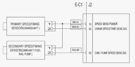
Schematic for speed/timing sensor
When the engine is cranking, the ECM uses the signal from the
speed/timing sensor in the fuel injection pump. When the engine is
running the ECM uses the signal from the speed/timing sensor on the
crankshaft. This speed/timing sensor is the primary source of the engine
position.
Pressure Sensors - The boost pressure sensor and the engine oil pressure
sensor are active sensors. The boost pressure sensor provides the ECM
with a measurement of inlet manifold pressure in order to control the
air/fuel ratio. This will reduce the engine smoke during transient
conditions. The operating range of the boost pressure sensors: For
standard power engines, the range is up to the following - 339 kPa
(49.169 psi) / For all high power engine, the range is up to the
following - 440 kPa (63.818 psi).
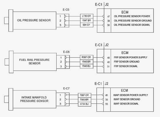
Schematic for pressure sensors
The engine oil pressure sensor provides the ECM with a measurement of
engine oil pressure. The ECM can warn the operator of possible
conditions that can damage the engine. This includes the detection of an
oil filter that is blocked. The operating range for the engine oil
pressure sensor - 55 kPa to 339 kPa (8 psi to 50 psi).
Temperature Sensors - The air inlet temperature sensor and the coolant
temperature sensor are passive sensors. Each sensor provides a
temperature input to the ECM. The ECM controls following operations:
Fuel delivery, Injection timing.
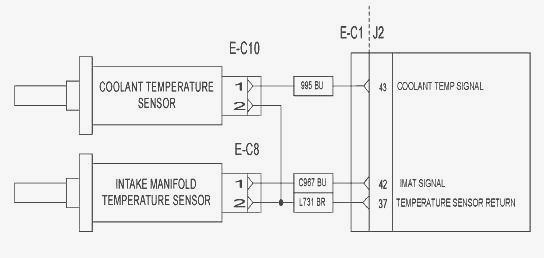
Schematic for the temperature sensors
The operating range for the sensors - 40C to 150C (40F to 302F). The
sensors are also used for engine monitoring.
Power Sources - The 1106 Perkins 6 cylinder Engine supplies power to the
ECM. The ECM powers the following components: All sensors on the engine,
The solenoid for the fuel Injection Pump, The solenoid for the Waste
gate (optional), Diagnostic connector, Electronic unit injectors. The
glow plugs are powered directly from the battery
ECM Power Supply - The power supply to the ECM and the system is drawn
from the 24 volt or the 12 volt battery. The power supply for the ECM
has the following components: Battery, disconnect switch, Key start
switch, Fuses, Ground bolt, ECM connector, Machine interface connector.
The Schematic for the ECM shows the main components for a typical power
supply circuit. Battery voltage is normally connected to the ECM. The
input from the key start switch turns on the ECM. The wiring harness can
be bypassed for troubleshooting purposes. The display screen on the
electronic service tool can be used in order to check the voltage
supply.
Power Supply for the Pressure Sensors / for the Glow plugs - The ECM
supplies 5.0 ± 0.2 DC volts through the ECM connector to each sensor.
The power supply is protected against short circuits. A short in a
sensor or a wiring harness will not cause damage to the ECM.
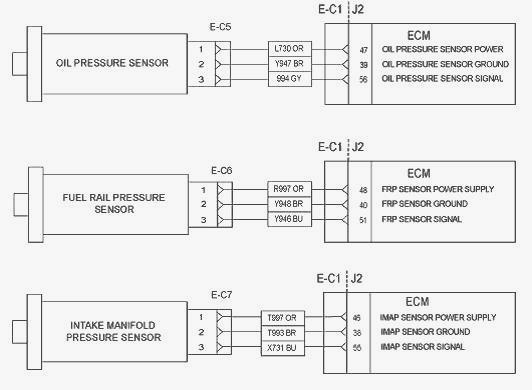
Schematic for pressure sensors
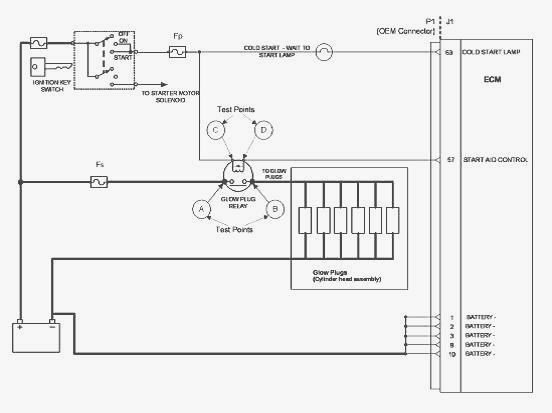
Schematic for the glow plugs
________________________________________________________________________________
________________________________________________________________________________________
 SPECS
SPECS LOADERS
 MAINTENANCE
 PROBLEMS
________________________________________________________________________________________
 MF 1523
 MF 1531
 MF 135
 MF 1547
 MF 1635
________________________________________________________________________________________
________________________________________________________________________________________
 231
231 231S
231S 235
235 240
240 241
241________________________________________________________________________________________
 255
255 265
265 274
274 285
285 375
375________________________________________________________________________________________
________________________________________________________________________________________
 916X Loader
 921X Loader
 926X Loader
 931X Loader
 936X Loader
________________________________________________________________________________________
 941X Loader
 946X Loader
 951X Loader
 956X Loader
 988 Loader
________________________________________________________________________________________
 1655
1655 GS1705
 1742
1742 2635
2635 4608
4608________________________________________________________________________________________
 1080
1080 1100
1100 2615
2615 3050
3050 3060
3060________________________________________________________________________________________
 4708
4708 5455
5455 5450
5450 5610
5610 5613
5613________________________________________________________________________________________
 DL95 Loader
 DL100 Loader
 DL120 Loader
 DL125 Loader
 DL130 Loader
________________________________________________________________________________________
 DL135 Loader
 DL250 Loader
 DL260 Loader
 L90 Loader
 L100 Loader
________________________________________________________________________________________
 6499
6499 7480
7480 7618
7618 7726
7726 1533
1533________________________________________________________________________________________
 2604H
2604H 2607H
2607H 4455
4455 4610M
4610M 4710
4710________________________________________________________________________________________
 L105E Loader
 L210 Loader
 1014 Loader
 1016 Loader
 1462 Loader
________________________________________________________________________________________
 1525 Loader
 1530 Loader
 232 Loader
 838 Loader
 848 Loader
________________________________________________________________________________________
 5712SL
 6713
6713 6715S
6715S 7475
7475 7615
7615________________________________________________________________________________________
 7716
7716 7724
7724 8240
8240 8650
8650 8732
8732________________________________________________________________________________________
 246 Loader
 1036 Loader
 1038 Loader
 1080 Loader
 856 Loader