
________________________________________________________________________________
1106 Perkins - Front Housing and Accessory Drive (Remove and Install)
Front Housing
Tool Part - A - 3 Bond, B - Guide Stud (M8 by 70 mm), C – Setscrews (M10
by 50 mm), D - Straight Edge. Remove:
- the fan. If necessary, remove the alternator.
- the front pulley. Drain the coolant into a suitable container for
storage or disposal.
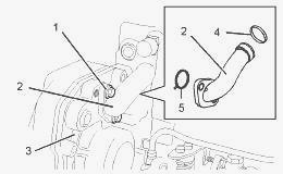
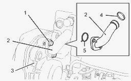
- the two setscrews (1) that secure the bypass tube (2) to the front
housing (3).
- the bypass tube (2) from the cylinder head.
- the O-rings (4) and (5) from the bypass tube (2). Discard the O-rings.
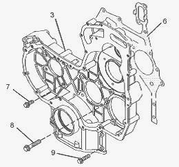
- the setscrews (7), (8) and (9) from the front housing (3). The
setscrews are three different lengths. Note the positions of the
different setscrews.
- the front housing (3) from the 1106 Perkins cylinder block.
- the joint (6). Discard the joint.
- the thrust washer from the cylinder block.
Keep all parts clean from contaminants. Contaminants may cause rapid
wear and shortened component life. Ensure that the front housing is
clean and free from damage. If necessary, replace the front housing.
Install:
- blanking plugs to a new front housing. Use Tooling (A) to seal all
D-plugs. Check the condition of the crankshaft front seal. If the front
seal is damaged, remove the front seal from the front housing. Clean all
the mating surfaces of the cylinder block.
- the thrust washer (10) into the recess in the cylinder block.
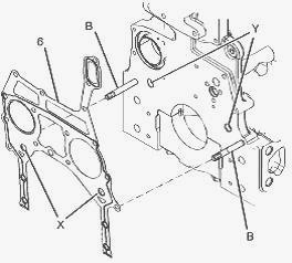
- Tooling (B) to the cylinder block. Refer to Illustration. Align a new
joint (6) with Tooling (B). Install the joint to the cylinder block.
Ensure that two circular tabs (X) on the joint are engaged in the two
holes (Y) in the cylinder block.
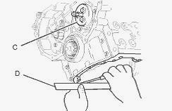
- Tooling (C) to the cylinder block.
- the front housing over Tooling (B) and Tooling (C) onto the 1106D
Perkins motor cylinder block.
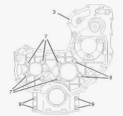
(7) M8 by 20 mm (8) M8 by 35 mm (9) M8 by 25 mm
- the four setscrews (9) to the front housing (3) finger tight. Remove
Tooling (B). Loosely install the setscrews (7) and (8). Refer to
Illustration for the correct position of the setscrews. Align the bottom
face of the front housing (3) to the lower machined face of the cylinder
block. Use a Tooling and a feeler gauge in order to check the alignment
between the front housing and the cylinder block.
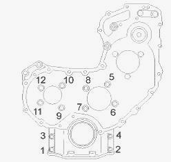
Tighten the setscrews (6), (7) and (8) in the sequence that is shown in
illustration to a torque of 28 Nm (20 lb ft). Ensure that the housing
and the cylinder block are correctly aligned. Remove Tooling (C) from
the cylinder block. If necessary, install a new crankshaft front seal.
Install:
- two new O-ring seals (4) and (5) to the bypass tube (1). Use Tooling
in order to lubricate the O-ring seals.
- the bypass tube (2) to the 1106 Perkins cylinder head. Install the two
setscrews (1). Tighten the setscrews to a torque of 22 Nm (16 lb ft).
Fill the cooling system with coolant.
- the fuel injection pump.
- the timing gears. If the engine has an accessory drive, install the
accessory drive.
- the engine oil pan.
- the front pulley. If necessary, install the alternator.
- the fan.
Accessory Drive
Remove:
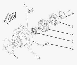
- the M10 Allen head screw (1) from the accessory drive housing (8).
- the five M8 Allen head screws (6) from the accessory drive housing
(8).
- the accessory drive housing (8) from the front housing.
- the circlip (2) from the accessory drive housing (8). Place the
accessory drive housing (8) onto a suitable support. Press the assembly
of the gear (4) and the bearings (3) and (5) out of the accessory drive
housing (8). Use a suitable puller in order to remove the bearings (3)
and (5) from the gear (4).
- the O-ring seal (7) from the accessory drive housing (8). Discard the
O-ring seal.
Inspect the condition of the teeth and the splines of the gear (4) for
wear or damage. Inspect the bearings (3) and (5), the circlip (2), and
the front housing for wear or damage. Replace any components that are
worn or damaged. Apply a small continuous bead of Tooling to the inner
surface (X) of the bearing (5). Place the gear shaft on a suitable
support. Press on the inner race of the bearing (5) until the bearing
(5) is against the shoulder of the gear (4). Remove any excess sealant.
Apply a small continuous bead of Tooling to the inner surface (Z) of the
bearing (3). Place the front face of the inner race of the bearing (3)
onto a suitable support. Press the shaft of the gear (4) into the
bearing (3) until the shoulder of the gear is against the bearing.
Remove any excess sealant.
Apply a small continuous bead of Tooling to the outer surface (Y) of the
bearing (5). Place the accessory drive housing (8) on a suitable
support. Press the assembly of the gear (4) and the bearings (3) and (5)
into the accessory drive housing. Ensure that the bearing (5) is against
the front face of the recess in the accessory drive housing (8). Remove
any excess sealant.
Install the circlip (2) into the groove in the accessory drive housing
(8). Ensure that the circlip (2) is correctly positioned in the groove.
Lightly lubricate a new O-ring seal (7) with Tooling and install the
O-ring seal into the groove in the accessory drive housing (8). Inspect
the bore in the front housing (not shown) for damage. If necessary,
replace the front housing. Lightly lubricate the bearing (3), the
bearing (5), and the gear (4) with clean engine lubricating oil. Install
the assembly of the accessory drive to the front housing.
Apply Tooling to the Allen head screws (1) and (6). Install the five M8
Allen head screws (6) to the accessory drive housing (8). Install the
M10 Allen head screw (1) to the accessory drive housing (8). Tighten the
Allen head screws to a torque of 22 Nm (16 lb ft). Ensure that there is
tactile backlash between the idler gear and the accessory drive gear.
________________________________________________________________________________
________________________________________________________________________________________
 SPECS
SPECS LOADERS
 MAINTENANCE
 PROBLEMS
________________________________________________________________________________________
 MF 1523
 MF 1531
 MF 135
 MF 1547
 MF 1635
________________________________________________________________________________________
________________________________________________________________________________________
 231
231 231S
231S 235
235 240
240 241
241________________________________________________________________________________________
 255
255 265
265 274
274 285
285 375
375________________________________________________________________________________________
________________________________________________________________________________________
 916X Loader
 921X Loader
 926X Loader
 931X Loader
 936X Loader
________________________________________________________________________________________
 941X Loader
 946X Loader
 951X Loader
 956X Loader
 988 Loader
________________________________________________________________________________________
 1655
1655 GS1705
 1742
1742 2635
2635 4608
4608________________________________________________________________________________________
 1080
1080 1100
1100 2615
2615 3050
3050 3060
3060________________________________________________________________________________________
 4708
4708 5455
5455 5450
5450 5610
5610 5613
5613________________________________________________________________________________________
 DL95 Loader
 DL100 Loader
 DL120 Loader
 DL125 Loader
 DL130 Loader
________________________________________________________________________________________
 DL135 Loader
 DL250 Loader
 DL260 Loader
 L90 Loader
 L100 Loader
________________________________________________________________________________________
 6499
6499 7480
7480 7618
7618 7726
7726 1533
1533________________________________________________________________________________________
 2604H
2604H 2607H
2607H 4455
4455 4610M
4610M 4710
4710________________________________________________________________________________________
 L105E Loader
 L210 Loader
 1014 Loader
 1016 Loader
 1462 Loader
________________________________________________________________________________________
 1525 Loader
 1530 Loader
 232 Loader
 838 Loader
 848 Loader
________________________________________________________________________________________
 5712SL
 6713
6713 6715S
6715S 7475
7475 7615
7615________________________________________________________________________________________
 7716
7716 7724
7724 8240
8240 8650
8650 8732
8732________________________________________________________________________________________
 246 Loader
 1036 Loader
 1038 Loader
 1080 Loader
 856 Loader