
________________________________________________________________________________
1106 Perkins engine - Fuel system (Test and inspect)
Fuel System - Inspect
A problem with the components that transport fuel to the 1106 Perkins
engines can cause low fuel pressure. This can decrease engine
performance. Check the fuel level in the fuel tank. Ensure that the vent
in the fuel cap is not filled with dirt. Check all fuel lines for fuel
leakage. The fuel lines must be free from restrictions and faulty bends.
Verify that the fuel return line is not collapsed.
Install new fuel filters. Cut the old filter open with a suitable filter
cutter. Inspect the filter for excess contamination. Determine the
source of the contamination. Make the necessary repairs. Operate the
hand priming pump (if equipped). If excessive resistance is felt, check
that there is fuel in the fuel return line to the tank.
Air in Fuel - Test
This procedure checks for air in the 1106 Perkins engine fuel system.
This procedure also assists in finding the source of the air. Examine
the fuel system for leaks. Check the fuel level in the fuel tank. Air
can enter the fuel system on the suction side between the fuel transfer
pump and the fuel tank.Install a suitable fuel flow tube with a visual
sight gauge in the fuel return to tank line. When possible, install the
fuel flow tube in a straight section of the fuel line that is at least
304.8 mm (12 inches) long. Do not install the fuel flow tube near the
following devices that create turbulence: Elbows, Relief valves, Check
valves.
Observe the fuel flow during engine cranking. Look for air bubbles in
the fuel. If there is no fuel that is present in the fuel flow tube,
prime the fuel system. If the tractor engine starts, check for air in
the fuel at varying engine speeds. When possible, operate the engine
under the conditions which have been suspect.
A steady stream of small bubbles with a diameter of approximately 1.60
mm (0.063 inch) is an acceptable amount of air in the fuel. Bubbles with
a diameter of approximately 6.35 mm (0.250 inch) are also acceptable if
there is two seconds to three seconds intervals between bubbles.
Excessive air bubbles in the fuel are not acceptable.
If excessive air is seen in the fuel flow tube in the fuel return line,
install a second fuel flow tube at the inlet to the fuel transfer pump.
If a second fuel flow tube is not available, move the fuel flow tube
from the fuel return line and install the fuel flow tube at the inlet to
the fuel transfer pump. Observe the fuel flow during engine cranking.
Look for air bubbles in the fuel. If the diesel engine starts, check for
air in the fuel at varying engine speeds.
If excessive air is not seen at the inlet to the fuel transfer pump, the
air is entering the system after the fuel transfer pump. If excessive
air is seen at the inlet to the fuel transfer pump, air is entering
through the suction side of the fuel system. To avoid damage, do not use
more than 55 kPa (8 psi) to pressurize the fuel tank. Pressurize the
fuel tank to 35 kPa (5 psi). Do not use more than 55 kPa (8 psi) in
order to avoid damage to the fuel tank.
Check for leaks in the fuel lines between the fuel tank and the fuel
transfer pump. Repair any leaks that are found. If the source of the air
is not found, disconnect the supply line from the fuel tank and connect
an external fuel supply to the inlet of the fuel transfer pump. If this
corrects the problem, repair the fuel tank or the stand pipe in the fuel
tank.
Finding Top Center Position for No.1 Piston - Remove the front cover.
Use Tooling in order to rotate the crankshaft until the hole (X) in the
camshaft gear (1) aligns with the hole in the front housing.
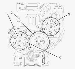
Install Tooling through the hole (X) in the camshaft gear (1) into the
front housing. Use Tooling in order to lock the camshaft in the correct
position.
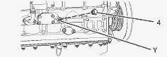
Remove the plug (4) from the cylinder block. Install Tooling into the
hole (Y) in the cylinder block. Use Tooling in order to lock the
crankshaft in the correct position.
Fuel Injection Timing - Check
Removal of the fuel injection pump. The bolts that hold the fuel
injection pump to the front housing are loosened. Set the number one
piston at the top center piston on the compression stroke. Carefully
remove the fuel injection pump from the front housing.
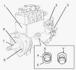
To check the fuel injection pump timing - Position Tooling onto the
shaft (8) of the fuel injection pump. Align the lever of Tooling with
the key slot (7). Engage the lever into the key slot. Insert the locking
pin of Tooling into the hole (6) in fuel injection pump. If the locking
pin can be inserted into the hole, the fuel injection pump timing is
correct. If the locking pin cannot be inserted into the hole, the fuel
injection pump timing is not correct. If the fuel injection pump timing
has been lost follow Steps in order to reset the fuel injection pump
timing.
If necessary, loosen the locking screw (4) on the fuel injection pump.
Slide the spacer (5) into position (X). Tighten the locking screw (4) to
a torque of 9 Nm (80 lb in). This will prevent the locking screw from
tightening against the shaft (8). The fuel injection pump is now
unlocked. Position Tooling onto the shaft (8) of the fuel injection
pump. Align the lever of Tooling with the key slot (7) in the fuel
injection pump. Engage the lever into the key slot.
Use the lever of Tooling to rotate the shaft (8) until the pin of
Tooling can be engaged into the hole (6). Engage the pin of Tooling into
the hole. Loosen the locking screw (4) in the fuel injection pump. Slide
the spacer (5) into position (Y). Tighten the locking screw (4) against
the shaft of the fuel injection pump to a torque of 9 Nm (80 lb in). The
fuel injection pump is now locked. Remove Tooling. Reinstall the fuel
injection pump to the front housing.
1106 Perkins Diesel Engine Fuel System -
Prime
Do not crank the motor continuously for more than 30 seconds. Allow the
starting motor to cool for two minutes before cranking the engine again.
If air enters the fuel system, the air must be purged from the fuel
system before the 1106 Perkins engines can be started.
Air can enter the fuel system when the
following events occur:
- The fuel tank is empty or the fuel tank has been partially drained.
- The low pressure fuel lines are disconnected.
- A leak exists in the low pressure fuel system.
- The fuel filter has been replaced.
Hand Fuel Priming Pump - Use the following procedures in order to remove
air from the fuel system: Ensure that the fuel system is in working
order. Restore the fuel supply. Operate the fuel priming pump (1). Count
the number of operations of the fuel priming pump. After 100 depressions
of the fuel priming pump stop. The engine fuel system should now be
primed and the engine should now be able to start. Do not loosen the
high pressure fuel line in order to purge air from the fuel system. This
procedure is not required. Operate the diesel engine starter and crank
the motor. After the engine has started, operate the engine at low idle
for a minimum of five minutes, immediately after air has been removed
from the fuel system.
Operating the engine for this period of time will help ensure that the
fuel system is free of air. After the engine has stopped, you must wait
for 60 seconds in order to allow the fuel pressure to be purged from the
high pressure fuel lines before any service or repair is performed on
the engine fuel lines. If necessary, perform minor adjustments. Repair
any leaks from the low pressure fuel system and from the cooling,
lubrication or air systems. Replace any high pressure fuel line that has
leaked. If you inspect the engine in operation, always use the proper
inspection procedure in order to avoid a fluid penetration hazard.
Electric Fuel Priming Pump - Ensure that the fuel system is in working
order. Restore the fuel supply. The electric fuel priming pump will
operate for 90 seconds. If necessary the electric fuel priming pump can
be stopped during the 90 seconds of operation, by operation of the
switch. Turn the keyswitch to the “RUN” position. Operate the switch for
the electric priming pump. After 90 seconds of the electric fuel priming
pump operation the fuel system will be primed and the electric fuel
priming pump will turn off. The diesel motor should now be able to
start. Do not loosen the high pressure fuel line in order to purge air
from the fuel system. This procedure is not required.
Operate the engine starter and crank the engine. After the engine has
started, operate the engine at low idle for a minimum of five minutes,
immediately after air has been removed from the fuel system. Operating
the engine for this period of time will help ensure that the fuel system
is free of air. After the engine has stopped, you must wait for 60
seconds in order to allow the fuel pressure to be purged from the high
pressure fuel lines before any service or repair is performed on the
engine fuel lines. If necessary, perform minor adjustments. Repair any
leaks from the low pressure fuel system and from the cooling,
lubrication or air systems. Replace any high pressure fuel line that has
leaked. If you inspect the engine in operation, always use the proper
inspection procedure in order to avoid
a fluid penetration hazard.
________________________________________________________________________________
________________________________________________________________________________________
 SPECS
SPECS LOADERS
 MAINTENANCE
 PROBLEMS
________________________________________________________________________________________
 MF 1523
 MF 1531
 MF 135
 MF 1547
 MF 1635
________________________________________________________________________________________
________________________________________________________________________________________
 231
231 231S
231S 235
235 240
240 241
241________________________________________________________________________________________
 255
255 265
265 274
274 285
285 375
375________________________________________________________________________________________
________________________________________________________________________________________
 916X Loader
 921X Loader
 926X Loader
 931X Loader
 936X Loader
________________________________________________________________________________________
 941X Loader
 946X Loader
 951X Loader
 956X Loader
 988 Loader
________________________________________________________________________________________
 1655
1655 GS1705
 1742
1742 2635
2635 4608
4608________________________________________________________________________________________
 1080
1080 1100
1100 2615
2615 3050
3050 3060
3060________________________________________________________________________________________
 4708
4708 5455
5455 5450
5450 5610
5610 5613
5613________________________________________________________________________________________
 DL95 Loader
 DL100 Loader
 DL120 Loader
 DL125 Loader
 DL130 Loader
________________________________________________________________________________________
 DL135 Loader
 DL250 Loader
 DL260 Loader
 L90 Loader
 L100 Loader
________________________________________________________________________________________
 6499
6499 7480
7480 7618
7618 7726
7726 1533
1533________________________________________________________________________________________
 2604H
2604H 2607H
2607H 4455
4455 4610M
4610M 4710
4710________________________________________________________________________________________
 L105E Loader
 L210 Loader
 1014 Loader
 1016 Loader
 1462 Loader
________________________________________________________________________________________
 1525 Loader
 1530 Loader
 232 Loader
 838 Loader
 848 Loader
________________________________________________________________________________________
 5712SL
 6713
6713 6715S
6715S 7475
7475 7615
7615________________________________________________________________________________________
 7716
7716 7724
7724 8240
8240 8650
8650 8732
8732________________________________________________________________________________________
 246 Loader
 1036 Loader
 1038 Loader
 1080 Loader
 856 Loader