
________________________________________________________________________________
1106 Perkins engine - Inlet and Exhaust Valves (Remove and Install)
Remove the cylinder head. Clean the bottom face of the cylinder head.
Check the depth of the valves below the face of the cylinder head before
the valve springs are removed. Place a temporary identification mark on
the heads of the valves in order to identify the correct position. Inlet
valves have a recess in the center of the head. Use a suitable lifting
device to position the cylinder head with the valve springs upward. The
weight of the cylinder head is approximately 65 kg (143 lb). Ensure that
the cylinder head is kept on a clean, soft surface in order to prevent
damage to the machined face.
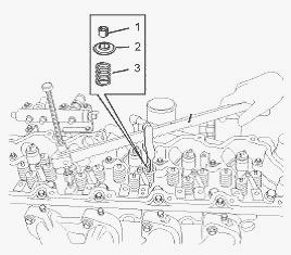
Install Tooling in position on the cylinder head in order to compress
the appropriate valve spring (3). Apply sufficient pressure to Tooling
in order to remove the valve keepers (1). Slowly release the pressure on
Tooling.
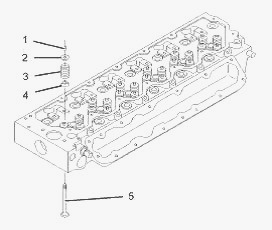
Remove the valve spring retainer (2). Remove the valve spring (3).
Repeat steps for the remaining valves. Remove Tooling. Remove the valve
stem seals (4). Use a suitable lifting device to carefully turn over the
cylinder head. Remove the valves (5).
Clean all components of the cylinder head assembly. Ensure that all
ports, all coolant passages and all lubrication passages in the cylinder
head are free from debris. Follow Steps to inspect the components of the
cylinder head assembly. Replace any components that are worn or damaged.
Inspect the cylinder head for wear and for damage. Inspect the valve
seats for wear and for damage. Inspect the valve guides for wear and for
damage. Inspect the valves for wear and for damage. Inspect the valve
springs (3) for damage and for the correct length.
Lubricate the stems of the valves (5) with clean engine oil. Install the
valves (5) in the appropriate positions in the cylinder head. Check the
depth of the valves below the face of the cylinder head. Use a suitable
lifting device to carefully turn over the cylinder head. The weight of
the cylinder head is approximately 65 kg (143 lb). Ensure that all of
the valves remain in place. Install new valve stem seals (4) onto each
of the valve guides. Install the valve spring (3) onto the cylinder
head. Position the valve spring retainer (2) on the valve spring (3).
Install Tooling in the appropriate position on the cylinder head in
order to compress the valve spring (3). Apply sufficient pressure to
Tooling in order to install the valve keepers (1). Carefully release the
pressure on Tooling. Repeat steps for the remaining valves. Remove
Tooling from the cylinder head. Use a suitable lifting device to
position the cylinder head on a support. Ensure that the heads of the
valves are not obstructed. Gently strike the top of the valves with a
soft hammer in order to ensure that the valve keepers (1) are properly
installed. Install the cylinder head.
Inlet and Exhaust Valve Springs - Remove and
Install
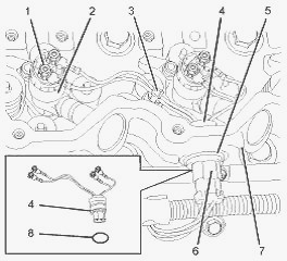
Follow Steps to remove the harness assemblies for the electronic unit
injectors. Place a temporary identification mark on the connections (1)
for the harness assembly (4) for the electronic unit injectors (2). Use
a deep socket to remove the connections (1) from the electronic unit
injectors (2). Cut the cable ties (3). Disconnect the plug (6) from the
harness assembly (4). Use Tooling to remove the circlip (5). From the
outside of the valve mechanism cover base (7), push the harness assembly
(4) inward. Withdraw the harness assembly from the valve mechanism cover
base. Remove the O-ring seal (8) from the harness assembly (4). Discard
the O-ring seal. Repeat Steps in order to remove the remaining harness
assemblies.
Follow Steps to position the appropriate piston at top dead center.
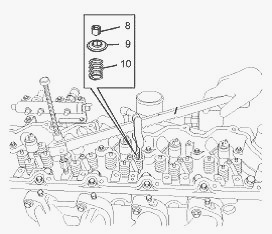
Install Tooling in position on the cylinder head in order to compress a
valve spring (10) for the appropriate piston. Use Tooling in order to
compress the valve spring (10) and open the valve slightly. Do not
compress the spring so that the valve spring retainer (9) touches the
valve stem seal.
Use Tooling in order to rotate the crankshaft carefully, until the
piston touches the valve. Not use excessive force to turn the
crankshaft. The use of force can result in bent valve stems. Continue to
rotate the crankshaft and gradually release the pressure on Tooling
until the piston is at the top dead center position. The valve is now
held in a position that allows the valve spring to be safely removed.
Valve springs must be replaced in pairs for the inlet valve or the
exhaust valve of each cylinder. If all valve springs require replacement
the procedure can be carried out on two cylinders at the same time. The
procedure can be carried out on the following pairs of cylinders. 1 with
6, 2 with 5, and 3 with 4. Ensure that all of the valve springs are
installed before changing from one pair of cylinders to another pair of
cylinders. Apply sufficient pressure to Tooling in order to allow
removal of the valve keepers (8).
Do not compress the spring so that the valve spring retainer (9) touches
the valve stem seal. Remove the valve keepers (8). Slowly release the
pressure on Tooling. Remove the valve spring retainer (9) and remove the
valve spring (10). If necessary, remove the valve stem seals. Repeat
Steps to remove the remaining valve springs from the appropriate
cylinder.
Inspect the valve springs (10) for damage and for the correct length. If
necessary, install a new valve stem seal onto the valve guide. The outer
face of the valve guide must be clean and dry before installing the
valve stem seal. Install the valve spring (10) onto the cylinder head.
Position the valve spring retainer (9) on the valve spring (10). Install
Tooling in the appropriate position on the cylinder head in order to
compress the valve spring (10).
Apply sufficient pressure to Tooling in order to install the valve
keepers (8). Do not compress the spring so that the valve spring
retainer (9) touches the valve stem seal. Install the valve spring
keepers. Carefully release the pressure on the Tooling. Repeat steps for
the remaining valves.
The valve keepers can be thrown from the valve when the valve spring
compressor is released. Ensure that the valve keepers are properly
installed on the valve stem. To help prevent personal injury, keep away
from the front of the valve keepers and valve springs during the
installation of the valves.
Remove the Tooling. Use Tooling to rotate the crankshaft through
approximately 45 degrees. This will ensure that the appropriate valve is
clear of the piston. Lightly strike the top of the valve with a soft
hammer in order to ensure that the valve keepers (10) are properly
installed. If all valve springs require replacement the procedure can be
carried out on two cylinders at the same time. The procedure can be
carried out on the following cylinders. 1 and 6, 2 and 5, and 3 and 4.
Remember that the crankshaft must not be turned while the valve springs
are removed. Ensure that all of the valve springs are installed before
changing from one pair of cylinders to the other pair of cylinders. If
all valve springs do not require replacement, the springs must be
replaced in pairs.
Follow Steps to install the harness assemblies for the electronic unit
injectors. Ensure that the harness assembly (4) for the electronic unit
injectors and the bore in the valve mechanism cover base (7) are clean
and free from damage. Replace any damaged components. Use Tooling to
lubricate a new O-ring seal. Install the new O-ring seal (8) onto the
harness assembly (4) for the electronic unit injectors. From the inside
of the valve mechanism cover base (7), push the harness assembly (4)
into the valve mechanism cover base. Use Tooling to install the circlip
(5). Connect the plug (6) to the harness assembly (4) for the electronic
unit injectors. Use a deep socket to install the connections (1) to the
electronic unit injectors (2). Use Tooling to tighten the connections to
a torque of 2.5 Nm (22 lb in). Install a new cable tie (3). Ensure that
cable ties to OE specification are used. Repeat Steps for the remaining
harness assemblies. Install the rocker shaft assembly.
________________________________________________________________________________
________________________________________________________________________________________
 SPECS
SPECS LOADERS
 MAINTENANCE
 PROBLEMS
________________________________________________________________________________________
 MF 1523
 MF 1531
 MF 135
 MF 1547
 MF 1635
________________________________________________________________________________________
________________________________________________________________________________________
 231
231 231S
231S 235
235 240
240 241
241________________________________________________________________________________________
 255
255 265
265 274
274 285
285 375
375________________________________________________________________________________________
________________________________________________________________________________________
 916X Loader
 921X Loader
 926X Loader
 931X Loader
 936X Loader
________________________________________________________________________________________
 941X Loader
 946X Loader
 951X Loader
 956X Loader
 988 Loader
________________________________________________________________________________________
 1655
1655 GS1705
 1742
1742 2635
2635 4608
4608________________________________________________________________________________________
 1080
1080 1100
1100 2615
2615 3050
3050 3060
3060________________________________________________________________________________________
 4708
4708 5455
5455 5450
5450 5610
5610 5613
5613________________________________________________________________________________________
 DL95 Loader
 DL100 Loader
 DL120 Loader
 DL125 Loader
 DL130 Loader
________________________________________________________________________________________
 DL135 Loader
 DL250 Loader
 DL260 Loader
 L90 Loader
 L100 Loader
________________________________________________________________________________________
 6499
6499 7480
7480 7618
7618 7726
7726 1533
1533________________________________________________________________________________________
 2604H
2604H 2607H
2607H 4455
4455 4610M
4610M 4710
4710________________________________________________________________________________________
 L105E Loader
 L210 Loader
 1014 Loader
 1016 Loader
 1462 Loader
________________________________________________________________________________________
 1525 Loader
 1530 Loader
 232 Loader
 838 Loader
 848 Loader
________________________________________________________________________________________
 5712SL
 6713
6713 6715S
6715S 7475
7475 7615
7615________________________________________________________________________________________
 7716
7716 7724
7724 8240
8240 8650
8650 8732
8732________________________________________________________________________________________
 246 Loader
 1036 Loader
 1038 Loader
 1080 Loader
 856 Loader