
________________________________________________________________________________
1106 Perkins Engine - Oil Cooler (Remove and install)
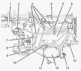
Engine oil cooler with a blanking plate
Remove the bracket for the Electronic Control Module. Drain the coolant
from the cooling system into a suitable container. Place a suitable
container below the engine oil cooler in order to catch any fluids that
might be spilled. If the engine has a left hand side oil filter, remove
the oil filter base. If the engine has a right hand side oil filter,
follow Steps to remove the blanking plate (12). Remove the four
setscrews (11). Remove the blanking plate (12). Remove the joint.
Discard the joint. Make temporary identification marks on the plastic
tube assemblies (3) in order to show the correct position of the tube
assemblies. Remove the plastic tube assemblies (3). Plug all plastic
tube assemblies with new plugs. Cap all open ports with new caps.
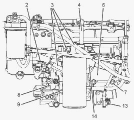
Engine oil cooler with a high mounted filter base
Follow Steps to disconnect the 1106 Perkins diesel motor wiring harness
(4). Disconnect the engine wiring harness (4) from the position sensor
(2) for the fuel injection pump. Disconnect the engine wiring harness
(4) from the solenoid (1) for the fuel injection pump. Disconnect the
engine wiring harness (4) from the oil pressure sensor (13). Cut the
cable ties that secure the engine wiring harness (4) to the assembly of
the oil cooler (6). Position the harness away from the assembly of the
oil cooler. Remove the tube assembly (9) for the fuel return from the
cylinder head (not shown) and from the transfer pump (8). Plug the tube
assembly with new plugs. Cap all open ports with new caps.
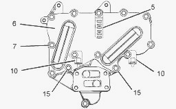
Engine oil cooler with a blanking plate or with a low mounted
filter base
If necessary, loosen the two setscrews (15). Remove the setscrews (7)
and remove the brackets (5) and (10) for the tube assemblies. Remove the
assembly of the oil cooler (6) from the cylinder block. The setscrews
are different lengths. Note the position of the different setscrews.
Note the location and the orientation of the brackets for the tube
assemblies.
Disassembly Procedure (Engine Oil Cooler with a Low Mounted Filter Base)
- Remove the two setscrews (15). Remove the cooler matrix (19) from the
spacer plate (17). Remove the joint (18). Discard the joint.
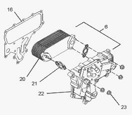
Disassembly Procedure (Engine Oil Cooler with a High Mounted Filter
Base) - Remove the four nuts (23) from the assembly of the oil cooler
(6). Remove the cooler matrix (20) from the housing (22). Remove the two
joints (21). Discard the joints.
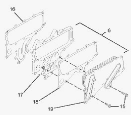
Assembly Procedure (Engine Oil Cooler with a Low Mounted Filter Base) -
Ensure that the cooler matrix (19) is clean and free from damage. Ensure
that the spacer plate (17) is clean and free from damage. Replace any
damaged components. Position a new joint (18) onto the spacer plate
(17). Install the cooler matrix (19) to the spacer plate. Install the
two setscrews (15) finger tight.
Position the brackets (5) and (10) onto the assembly of the oil cooler
(6). Install the setscrews (7). Ensure that brackets for the tube
assemblies are installed in the correct location and the correct
orientation. The setscrews are different lengths. Ensure that the
different setscrews are installed in the correct location. Install the
joint (16) to the assembly of the oil cooler (6). Push the setscrews (7)
through the holes in the joint. The holes in the joint have serrations
that hold the setscrews captive.
Assembly Procedure (Engine Oil Cooler with a High Mounted Filter Base) -
Ensure that the cooler matrix (20) and the housing (22) are clean and
free from damage. Replace any damaged components. Install two new joints
(21) to the cooler matrix (20). Install the cooler matrix (20) to the
housing (22). Install the four nuts (23) to the assembly of the oil
cooler (6). Tighten the nuts to a torque of 22 Nm (16 lb ft).
Install the setscrews (7) to the assembly of the oil cooler (6). Install
the joint (16) to the assembly of the oil cooler (6). Push the setscrews
(7) through the holes in the joint. Clean the joint face of the cylinder
block. Install the assembly of the oil cooler (6) to the cylinder block.
Tighten the setscrews (7) finger tight. If the engine has a high mounted
oil filter base, install the oil filter base (14) finger tight.
If the 1106 Perkins diesel motor has a low mounted oil filter base or a
blanking plate, tighten the setscrews to a torque of 22 Nm (16 lb ft) in
the sequence. If the engine has a high mounted oil filter base, tighten
the setscrews to a torque of 22 Nm (16 lb ft) in the. Tighten the
remaining setscrews that secure the oil filter base to a torque of 22 Nm
(16 lb ft). Remove the plugs from the tube assembly (9). Remove the caps
for the fuel return from the cylinder head and from the transfer pump
(8). Install the tube assembly (9) to the cylinder head and to the
transfer pump (8). Follow Steps in order to connect the engine wiring
harness (4).
Place the harness in position. Connect the 1106 Perkins diesel motor
wiring harness (4) to the position sensor (2) for the fuel injection
pump. Connect the engine wiring harness (4) to the oil pressure sensor
(13). Connect the engine wiring harness (4) to the solenoid (1) for the
fuel injection pump. Install new cable ties in order to secure the
engine wiring harness (4) to the assembly of the oil cooler (6). Remove
the plugs from all plastic tube assemblies (3). Remove the caps from the
appropriate ports. Install the plastic tube assemblies (3). If the
engine has a low mounted oil filter on the left hand side, install the
oil filter base.
If the engine has a right hand side oil filter, follow Steps to install
the blanking plate (12). Install the four setscrews (11) to the blanking
plate (12). Position a new joint (not shown) onto the blanking plate
(12). Install the assembly of the blanking plate to the assembly of the
oil cooler (6). Tighten the setscrews (11) to a torque of 22 Nm (16 lb
ft). Fill the cooling system to the correct level. Check the level of
the engine lubricating oil. Install the bracket for the Electronic
Control Module (ECM).
________________________________________________________________________________
________________________________________________________________________________________
 SPECS
SPECS LOADERS
 MAINTENANCE
 PROBLEMS
________________________________________________________________________________________
 MF 1523
 MF 1531
 MF 135
 MF 1547
 MF 1635
________________________________________________________________________________________
________________________________________________________________________________________
 231
231 231S
231S 235
235 240
240 241
241________________________________________________________________________________________
 255
255 265
265 274
274 285
285 375
375________________________________________________________________________________________
________________________________________________________________________________________
 916X Loader
 921X Loader
 926X Loader
 931X Loader
 936X Loader
________________________________________________________________________________________
 941X Loader
 946X Loader
 951X Loader
 956X Loader
 988 Loader
________________________________________________________________________________________
 1655
1655 GS1705
 1742
1742 2635
2635 4608
4608________________________________________________________________________________________
 1080
1080 1100
1100 2615
2615 3050
3050 3060
3060________________________________________________________________________________________
 4708
4708 5455
5455 5450
5450 5610
5610 5613
5613________________________________________________________________________________________
 DL95 Loader
 DL100 Loader
 DL120 Loader
 DL125 Loader
 DL130 Loader
________________________________________________________________________________________
 DL135 Loader
 DL250 Loader
 DL260 Loader
 L90 Loader
 L100 Loader
________________________________________________________________________________________
 6499
6499 7480
7480 7618
7618 7726
7726 1533
1533________________________________________________________________________________________
 2604H
2604H 2607H
2607H 4455
4455 4610M
4610M 4710
4710________________________________________________________________________________________
 L105E Loader
 L210 Loader
 1014 Loader
 1016 Loader
 1462 Loader
________________________________________________________________________________________
 1525 Loader
 1530 Loader
 232 Loader
 838 Loader
 848 Loader
________________________________________________________________________________________
 5712SL
 6713
6713 6715S
6715S 7475
7475 7615
7615________________________________________________________________________________________
 7716
7716 7724
7724 8240
8240 8650
8650 8732
8732________________________________________________________________________________________
 246 Loader
 1036 Loader
 1038 Loader
 1080 Loader
 856 Loader