
________________________________________________________________________________
1106 Perkins engine - Pistons and Connecting Rods (Disassemble and Assemble)
Disassembly Procedure
Remove the pistons and the connecting rods. Make a temporary mark on the
components of the piston and connecting rod assembly. This will ensure
that the components of each piston and connecting rod assembly can be
reinstalled in the original cylinder. Mark the underside of the piston
on the front pin boss. Do not interchange components.
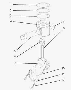
Remove:
- the two setscrews (12) and the connecting rod cap (11) from the
connecting rod (6). Discard the setscrews. Fracture split connecting
rods should not be left without the connecting rod caps installed. After
the disassembly procedure for the piston and connecting rod is
completed, carry out the assembly procedure and the installation
procedure as soon as possible.
- the lower bearing shell (10) from the connecting rod cap (11).
- the upper bearing shell (9) from the connecting rod (6). Keep the
bearing shells together.
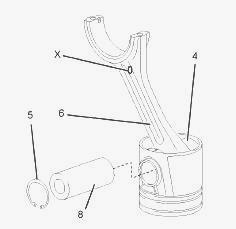
Place the piston and connecting rod assembly on a suitable surface with
the connecting rod upward. Use Tooling in order to remove the circlips
(5). The forged marks (X) may be on the front of the connecting rod
assembly, or on the rear of the connecting rod assembly. The forged
marks should not be used for the purposes of orientation.
Remove:
- the piston pin (8) and the connecting rod (6) from the piston (4). If
the piston pin cannot be removed by hand, heat the piston to a
temperature of 45 ± 5C (113 ± 9F). Do not use a torch to heat the
piston. Note the orientation of the connecting rod (6) and the piston
(4). Place the piston on a suitable surface with the crown upward.
- the compression rings (1) and (2), and the oil control ring (3) from
the piston (4). Identify the position and orientation of the compression
rings (1) and (2), and the oil control ring (3). Inspect the connecting
rod for wear or damage. If necessary, replace the connecting rod (6) or
replace the bush for the piston pin (7). If the connecting rod or the
bush for the piston pin are replaced, first identify the height grade of
the connecting rod. Repeat Steps to disassemble the remaining pistons
and connecting rods.
Assembly Procedure
Ensure that all components are clean and free from wear or damage. If
necessary, replace any components that are worn or damaged. If the
original piston is assembled, follow Steps to install the piston rings.
Position the spring for the oil control ring (3) into the oil ring
groove in the piston (4). The central wire must be located inside the
end of the spring.
Use Tooling to install the oil control ring (3) over the spring. Ensure
that the central wire is 180 degrees from the ring gap. Use Tooling to
install the intermediate compression ring (2) into the second groove in
the piston (4). The word “TOP” must be upward. The chamfer on the inner
face must be downward. Use Tooling to install the top compression ring
(1) into the top groove in the piston (4). The word “TOP” must be
upward.
Position the piston ring gaps at 120 degrees away from each other. A new
piston assembly is supplied with new piston rings. If the connecting rod
assembly (6), (7), (11) and (12) or the bush for the piston pin (7) is
replaced, ensure that the height grade of the connecting rod is correct.
Lubricate the bush for the piston pin (7) in the connecting rod and
lubricate the bore for the piston pin in the piston (4) with clean
engine oil.
Place the piston on a suitable surface with the crown downward.
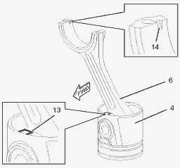
Install:
- the connecting rod (6) and the piston pin (8) to the piston (4).
Ensure that the square (13) on the piston, and the slot (14) on the
connecting rod are in the correct position. See illustration. If the
piston pin cannot be installed by hand, heat the piston to a temperature
of 45 ± 5C (113 ± 9F).
- the circlips (5) to the piston pin bore in the piston (4). Ensure that
the circlips are seated in the grooves in the piston.
- the upper bearing shell (9) into the connecting rod (6). Ensure that
the locating tab for the upper bearing shell is correctly seated in the
slot in the connecting rod.
- the lower bearing shell (10) into the connecting rod cap (11). Ensure
that the locating tab for the lower bearing shell is correctly seated in
the slot in the connecting rod cap. Repeat Steps for the remaining
piston and connecting rod assemblies.
- the pistons and the connecting rods.
________________________________________________________________________________
________________________________________________________________________________________
 SPECS
SPECS LOADERS
 MAINTENANCE
 PROBLEMS
________________________________________________________________________________________
 MF 1523
 MF 1531
 MF 135
 MF 1547
 MF 1635
________________________________________________________________________________________
________________________________________________________________________________________
 231
231 231S
231S 235
235 240
240 241
241________________________________________________________________________________________
 255
255 265
265 274
274 285
285 375
375________________________________________________________________________________________
________________________________________________________________________________________
 916X Loader
 921X Loader
 926X Loader
 931X Loader
 936X Loader
________________________________________________________________________________________
 941X Loader
 946X Loader
 951X Loader
 956X Loader
 988 Loader
________________________________________________________________________________________
 1655
1655 GS1705
 1742
1742 2635
2635 4608
4608________________________________________________________________________________________
 1080
1080 1100
1100 2615
2615 3050
3050 3060
3060________________________________________________________________________________________
 4708
4708 5455
5455 5450
5450 5610
5610 5613
5613________________________________________________________________________________________
 DL95 Loader
 DL100 Loader
 DL120 Loader
 DL125 Loader
 DL130 Loader
________________________________________________________________________________________
 DL135 Loader
 DL250 Loader
 DL260 Loader
 L90 Loader
 L100 Loader
________________________________________________________________________________________
 6499
6499 7480
7480 7618
7618 7726
7726 1533
1533________________________________________________________________________________________
 2604H
2604H 2607H
2607H 4455
4455 4610M
4610M 4710
4710________________________________________________________________________________________
 L105E Loader
 L210 Loader
 1014 Loader
 1016 Loader
 1462 Loader
________________________________________________________________________________________
 1525 Loader
 1530 Loader
 232 Loader
 838 Loader
 848 Loader
________________________________________________________________________________________
 5712SL
 6713
6713 6715S
6715S 7475
7475 7615
7615________________________________________________________________________________________
 7716
7716 7724
7724 8240
8240 8650
8650 8732
8732________________________________________________________________________________________
 246 Loader
 1036 Loader
 1038 Loader
 1080 Loader
 856 Loader