
________________________________________________________________________________
Sisu diesel engine - Spacer (MF 6400 tractors)
The spacer is an important part of the chassis. It links the engine and
the gearbox but also supports: the 4 WD shaft bearing (if fitted); the
right- and left-hand cab supports. The top profile can support a
6-cylinder Sisu diesel engine. At the front, a cover closes the gearbox
housing.
Removing - refitting the cover and replacing the lip seal
Disassemble the 6485, 6490, 6495, 6497, 6499 Massey Ferguson tractors
between the engine and the gearbox. Drain the oil from the gearbox.
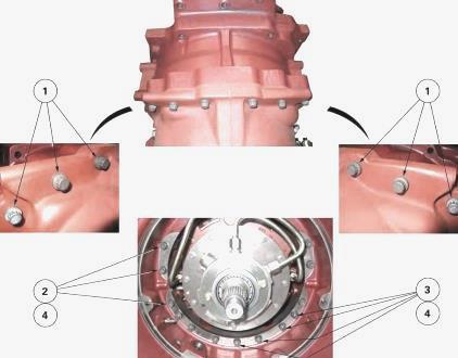
Removing the cover - Position the protector 3378012M2 on the mainshaft.
Remove the screws marking their dimensions and positions. Take off cover
(4). To remove, take out the cover and hold it in place using the tapped
holes and two locally made screws of sufficient length. If necessary,
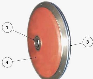
discard (Fig. 5): the O'ring (3); the lip seal (1).
Replacing the lip seal - Drive the seal (1) (Fig. 5) off the cover (4).
Thoroughly clean any dirt from the point where the seal meets the cover.
Lubricate the rim of the new seal. Use an improvised fitting drift
slightly smaller than the outside diameter of the seal to fit the seal
up against the cover. Grease the lip and rear cavity of the seal.
Refitting the cover - Clean and visually check all components. Replace
any defective parts. Lubricate and fit a new O’ring (3) (Fig. 5). On the
shaft, position the protector used at disassembly. Check the presence:
of locating pins on the spacer; of the shim (s) used to shim the clutch,
on the pump cover.
If the cover had to be replaced, check or even redo the shimming of the
PowerShuttle forward clutch. Smear the rim of the tapped holes with
Loctite 5206 or equivalent. Screw two diametrically opposed guide studs
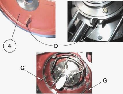
on to the spacer. Refit the cover (4), with the D finger in the slot of
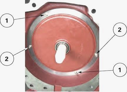
the pump body (Fig. 9). Refit the screws (1) (2) in their respective
positions (Fig. 10). Tighten to a torque of 36 - 46 Nm.
Remove the 3378012M2 protector. Top up the oil level in the housings.
Check it using the sight glass located at the rear left-hand side of the
rear axle. Assemble the tractor between the engine and the gearbox.
Check: tightness of the mating face; correct operation of the Power
Shuttle.
Removing - refitting the spacer
Disassemble 6485, 6490, 6495, 6497, 6499 Massey Ferguson tractors
between the Sisu engine and the gearbox. If necessary, move apart the
gearbox chassis reinforcements. Drain the oil from the gearbox and
centre housing. If necessary and depending on the case, move the fuel
tank apart from the gearbox, or remove it after draining.
Servicing on the cab - Split the cab from the supports on the front
rightand left-hand sides. Using two straps fitted to the lateral
handles, gently lift the front of the cab, while watching the rear
suspension.
Servicing on the right-hand side of the 6400 MF tractor - Remove the
cab/battery support fitted to the spacer. Remove: the flange and the
lubricating pipe connected to the rear axle; the supply pipe (17 bar)
and union coming from the control unit. Servicing on the left-hand side
of the tractor - Remove the front fuel tank support. Remove the cab
support connected to the spacer. After removing the supports, position
two suitable stands at the front and at each side of the cab.
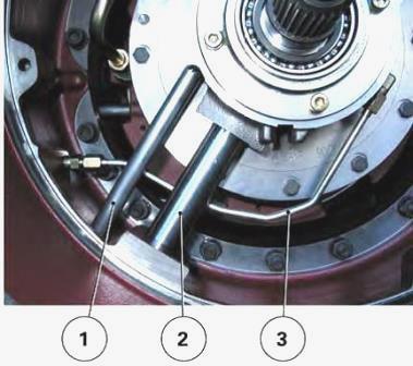
Removing the spacer - Remove cover (4). Remove the pipes (Fig. 12): 17
bar (1) low pressure; lubrication (2); diagnostics connector (3). Remove
the screws and nuts fixing the spacer to the gearbox. Mark their length
and position. Detach and split the spacer from the gearbox with the help
of an operator.
Refitting the spacer - Clean the components. Replace any defective
parts. Check the positioning and tightness of the studs on the gearbox.
Clean off any Loctite previously applied to the mating faces. Grease the
mating face of the spacer (gearbox side) with Loctite 5206 or
equivalent. Check the presence of locating pins.
Refit the spacer with the help of an operator. Fit washers (4). Lightly
smear the thread of the screws and nuts (Fig. 17) with Loctite 270 or
equivalent. Tighten them in the following manner: collar screw (1) to a
torque of 150 - 200 Nm; screws (2) and nuts (3) to a torque of 100 - 130
Nm. The union thread (1) and that of the diagnostic connector (2) are
lightly smeared with Loctite 542 or equivalent. Refit the pipes. If the
spacer had to be replaced, check or even redo the shimming of the
PowerShuttle forward clutch. Refit cover (4).
Refit: the left-hand cab support fitted to the spacer. Tighten the
screws to a torque of 200 - 260 Nm (Loctite 270); the front fuel tank
support. Tighten the screws to a torque of 160 - 210 Nm (Loctite 270).
Refit: the union and low pressure 17 bar pipe (2), the flange and
lubricating pipe (1). Refit the cab support to the spacer. Tighten the
screws to a torque of 200 - 260 Nm (Loctite 270). Fix the cab onto the
front supports. If removed, refit the fuel tank. Top up the oil level in
the housings. Check it using the sight glass located at the rear
left-hand side of the rear axle.
Assemble the tractor between the engine and the gearbox. If necessary,
position and adjust the chassis reinforcements. Check: the tightness of
the unions and mating face of the spacer; the correct operation of the
PowerShuttle and fuel gauge; automatic cab suspension.
________________________________________________________________________________
________________________________________________________________________________________
 SPECS
SPECS LOADERS
 MAINTENANCE
 PROBLEMS
________________________________________________________________________________________
 MF 1523
 MF 1531
 MF 135
 MF 1547
 MF 1635
________________________________________________________________________________________
________________________________________________________________________________________
 231
231 231S
231S 235
235 240
240 241
241________________________________________________________________________________________
 255
255 265
265 274
274 285
285 375
375________________________________________________________________________________________
________________________________________________________________________________________
 916X Loader
 921X Loader
 926X Loader
 931X Loader
 936X Loader
________________________________________________________________________________________
 941X Loader
 946X Loader
 951X Loader
 956X Loader
 988 Loader
________________________________________________________________________________________
 1655
1655 GS1705
 1742
1742 2635
2635 4608
4608________________________________________________________________________________________
 1080
1080 1100
1100 2615
2615 3050
3050 3060
3060________________________________________________________________________________________
 4708
4708 5455
5455 5450
5450 5610
5610 5613
5613________________________________________________________________________________________
 DL95 Loader
 DL100 Loader
 DL120 Loader
 DL125 Loader
 DL130 Loader
________________________________________________________________________________________
 DL135 Loader
 DL250 Loader
 DL260 Loader
 L90 Loader
 L100 Loader
________________________________________________________________________________________
 6499
6499 7480
7480 7618
7618 7726
7726 1533
1533________________________________________________________________________________________
 2604H
2604H 2607H
2607H 4455
4455 4610M
4610M 4710
4710________________________________________________________________________________________
 L105E Loader
 L210 Loader
 1014 Loader
 1016 Loader
 1462 Loader
________________________________________________________________________________________
 1525 Loader
 1530 Loader
 232 Loader
 838 Loader
 848 Loader
________________________________________________________________________________________
 5712SL
 6713
6713 6715S
6715S 7475
7475 7615
7615________________________________________________________________________________________
 7716
7716 7724
7724 8240
8240 8650
8650 8732
8732________________________________________________________________________________________
 246 Loader
 1036 Loader
 1038 Loader
 1080 Loader
 856 Loader