
________________________________________________________________________________
MF 3060, 3065 tractor Gearbox assembly
Removal and preparation
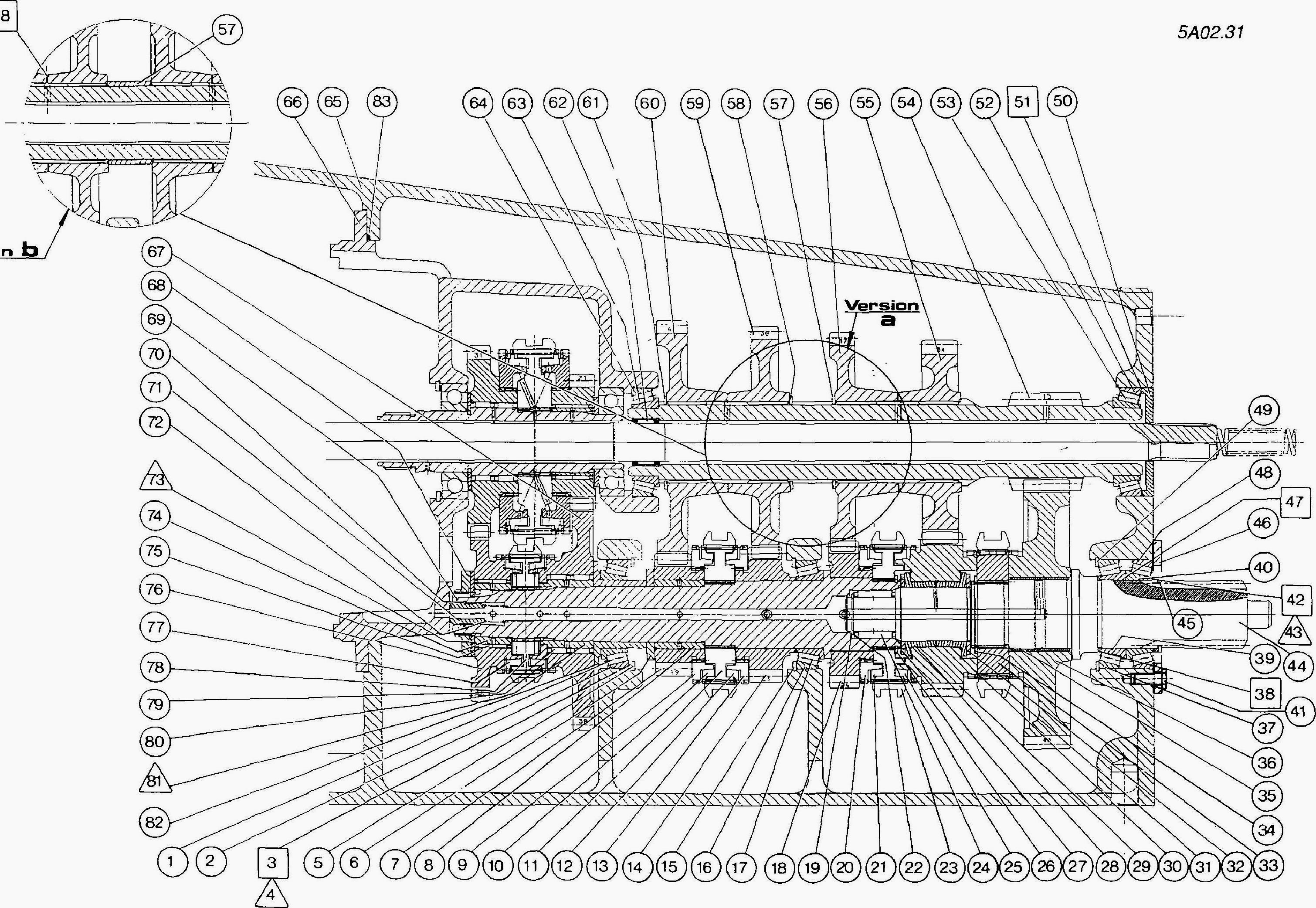
Fig.1
Split Massey Ferguson 3065, 3060, 3070, 3080 tractors between the
gearbox and the rear axle.
Place a sling under the gearbox (Fig.1). Split the tractor between the
gearbox and the engine or separate the gearbox from the engine. Remove
the PTO shaft.
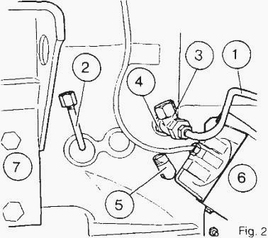
Fig.2
Remove:
- the PTO clutch hydraulic feed pipe,
- the engine clutch slave cylinder supply pipe,
- the T-piece and 1.5 bar valve,
- the 90; oil return pipe connection,
- the Datatronic sensor and its bracket (ii fitted).
- the LH cab support
Lay the gearbox on its LH side and lift it on to a suitable stand or
work bench. Remove the A/B range (4x4 gearbox) feed pipe (1) (17 bar)
(Fig.4).
Remove the bolts (2). (Fig. 4). On gearboxes fitted with a creeper
range, remove the control cable bracket and mark the position of the
centring bolt 3.
Remove the cover (4) and bolt (5). (Fig. 4)
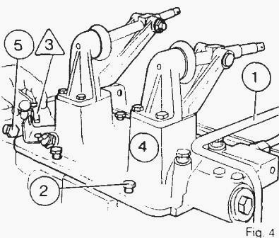
Fig. 4
Shifter rail and forks - Removal:
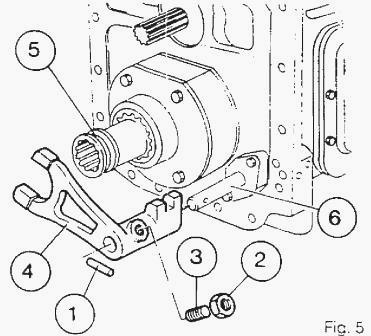
Fig.5

Fig.6
- Gearbox fitted with creeper range. Remove the pin (1), the locknut
(2), the adjustable setscrew (3). the fork (4) with the sleeve (5).
(Fig.5)
- Remove me plugs (1). the sonngs (2) and locking plungers (3) from
forks (5) and (6) (Fig.6)
- Slacken the castellated nut using spanner 3615334 M01.
- Engage 4th gear (4x2 gearbox) or 3rd gear (MF 3060, 3065 tractor 4 x 4
gearbox).
- Release the cone (24) on the shifter rail (7) using a bronze drift
(Fig.8).
- Remove the setscrew (8).
- Eject the plug forwards by tapping the end of the rail (7) (Fig. 9)
Remove:
- the bearing (15)
- the shifter rail (7) rearwards
- 1st and 2nd gear fork (5) and 3rd and 4th gear fork (6) the lock
assembly (25)
Disassemble:
- the castellated nut (21)
- the latch (22)
- the tapered bearing (23)
- the cone (24)
Remove:
- the screws (19)
- the piston (13)
- the High/Low range fork (20)
- the bolt and washer assembly (17) and the guide (18)
- the cylinder (10)
- Discard the seals (12) and (14) from piston (13) and the seal (11)
from the cylinder (10).
- The A/B fork (4) stays in the housing (MF 3060, 3065 tractor 4x4
gearbox).
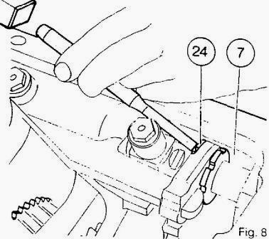
Fig.8
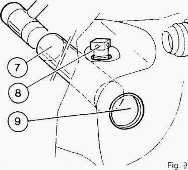
Fig.9
Input shaft housing - Removal:
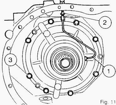
Fig. 11
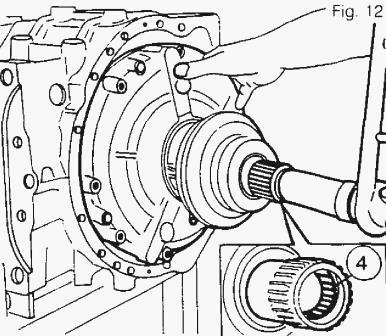
Fig. 12
- Immobilize the layshaft assembly using the locally made-up tool.
- Remove the drain pipe {1) from the clutch slave cylinder and the union
(2) on the housing (Fig. 11).
- Place a sling under the housing assembly, taking care to avoid
damaging the needle roller bearing (4) (Fig. 12).
- Remove the eight 10 mm diameter bolts (3) (Fig. 11). Note: It is not
necessary to remove the selector (5) (Fig. 13) in order to remove the
housing.
- Release and withdraw the housing assembly by tilting it to the left
(Fig 12). (Fig.13 and 14)
- Retrieve the locating dowel (8). Discard the oil seals (6) and (7).

Fig. 13
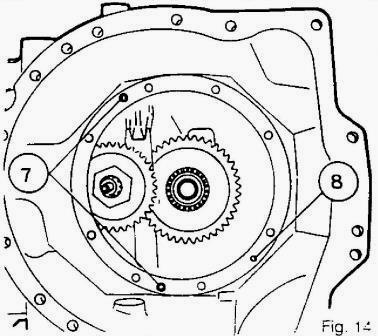
Fig. 14
Layshaft - Disassembly:
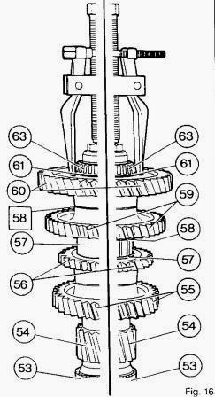
Fig.16
- Withdraw the layshaft complete,
- Remove the washer (50).
- Remove the shims [51].
- Remove the cup (52). Disassembly of shaft (54) (Fig.16).
- A new shaft fitting was introduced from serial number P345012 (version
b). MF 3065, 3060 Tractors prior to this number are fitted with version
a.
- Withdraw the taper roller bearings (53) and (63). Note: Keep the
bearings and cups in matched pairs for possible re-use.
- Remove the circlip (61).
- Remove 1st gear (60) and 2nd gear (59).
- Remove 1st gear (60). the shims [58] and 2nd gear (59).
- Remove circlips (58) and (57) (Fig. 16). b) Remove spacer (57)
- Remove 4th gear (56) (4x2 gearbox) and 3rd gear (55) (4x2 gearbox)
- Remove 3rd gear (56) (4x4 gearbox) and 4th gear (55) (4x4 gearbox).
- Drift out the needle roller bearing (62) (Fig. 17) and discard it.

Fig.17
MF 3060, 3065 tractor Creeper gearbox
Removal:
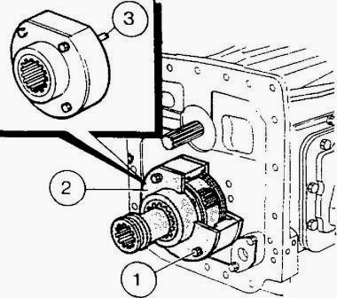
Fig.18
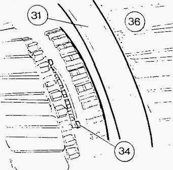
Fig.19
Remove the bolts (1).
Remove the creeper gearbox assembly (2). The locating dowels (3) are
held in the gearbox.
Output shaft - Disassembly:
- If the tractor is fitted with a creeper gearbox, see above.
- Remove the 3 bolts (41),
- Remove the lock plate (46).
- Remove the bearing cue (48).
- Keep the bearings and cups in pairs for possible re-use.
- Remove the circlip (45).
- Remove the spacer 43 and shims [42].
- Remove the taper roller bearing (40).
- Where shims have had to be inserted between bearings, remove the shim
adjuster(s) [47]
- Remove the roller bearing (39).
- Remove the shims [38],
- Engage the High/Low range coupler (31) (Fig. 19) on me Low range
pinion (36)
- Withdraw the shaft (44) rearwards.
- Remove the circlip (34) using tool MF 460 and discard it (Fig. 19).
- Remove the shaft,
- Through the inspection panel in the selector rail mechanism cover,
withdraw: the hub (33) and its coupler, the gear (29) (3rd gear 4x2
gearbox and 4th gear 4x4
gearbox), the synchromesh cup (25). the two thrust washers (32)-{27) and
the Low range gear (36).
- Remove the cup (37).
- Remove the circlip (49).
- Remove the circlip (19). the washer (22) and the needle roller bearing
(24).
________________________________________________________________________________
________________________________________________________________________________________
 SPECS
SPECS LOADERS
 MAINTENANCE
 PROBLEMS
________________________________________________________________________________________
 MF 1523
 MF 1531
 MF 135
 MF 1547
 MF 1635
________________________________________________________________________________________
________________________________________________________________________________________
 231
231 231S
231S 235
235 240
240 241
241________________________________________________________________________________________
 255
255 265
265 274
274 285
285 375
375________________________________________________________________________________________
________________________________________________________________________________________
 916X Loader
 921X Loader
 926X Loader
 931X Loader
 936X Loader
________________________________________________________________________________________
 941X Loader
 946X Loader
 951X Loader
 956X Loader
 988 Loader
________________________________________________________________________________________
 1655
1655 GS1705
 1742
1742 2635
2635 4608
4608________________________________________________________________________________________
 1080
1080 1100
1100 2615
2615 3050
3050 3060
3060________________________________________________________________________________________
 4708
4708 5455
5455 5450
5450 5610
5610 5613
5613________________________________________________________________________________________
 DL95 Loader
 DL100 Loader
 DL120 Loader
 DL125 Loader
 DL130 Loader
________________________________________________________________________________________
 DL135 Loader
 DL250 Loader
 DL260 Loader
 L90 Loader
 L100 Loader
________________________________________________________________________________________
 6499
6499 7480
7480 7618
7618 7726
7726 1533
1533________________________________________________________________________________________
 2604H
2604H 2607H
2607H 4455
4455 4610M
4610M 4710
4710________________________________________________________________________________________
 L105E Loader
 L210 Loader
 1014 Loader
 1016 Loader
 1462 Loader
________________________________________________________________________________________
 1525 Loader
 1530 Loader
 232 Loader
 838 Loader
 848 Loader
________________________________________________________________________________________
 5712SL
 6713
6713 6715S
6715S 7475
7475 7615
7615________________________________________________________________________________________
 7716
7716 7724
7724 8240
8240 8650
8650 8732
8732________________________________________________________________________________________
 246 Loader
 1036 Loader
 1038 Loader
 1080 Loader
 856 Loader