
________________________________________________________________________________
MF 3050, 3070 Tractor Gearbox Shifter rail, forks and Selector
Massey Ferguson 3070, 3050, 3125, 3105
tractors gearbox Shifter rail and forks Reassembly
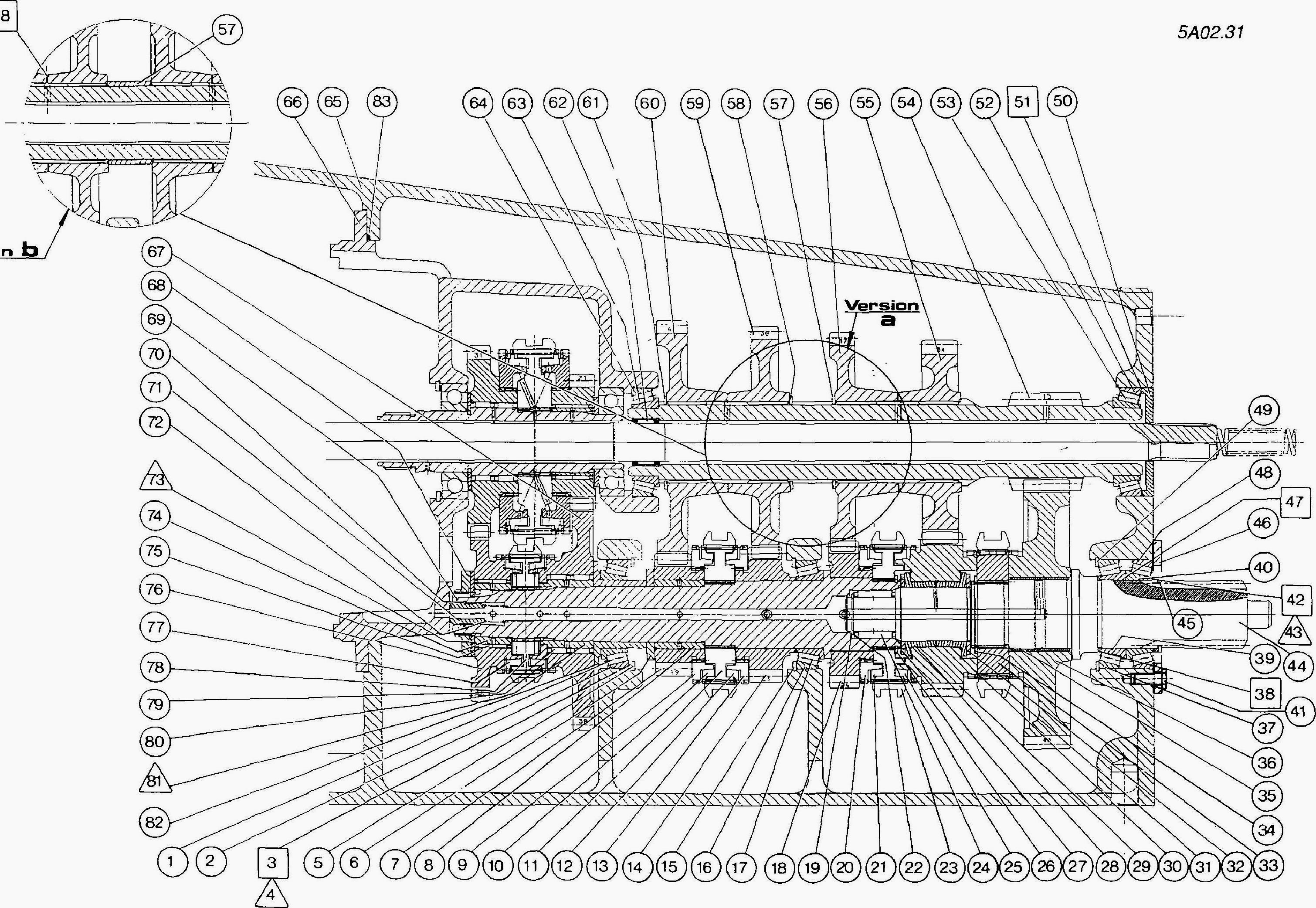
Fig.1
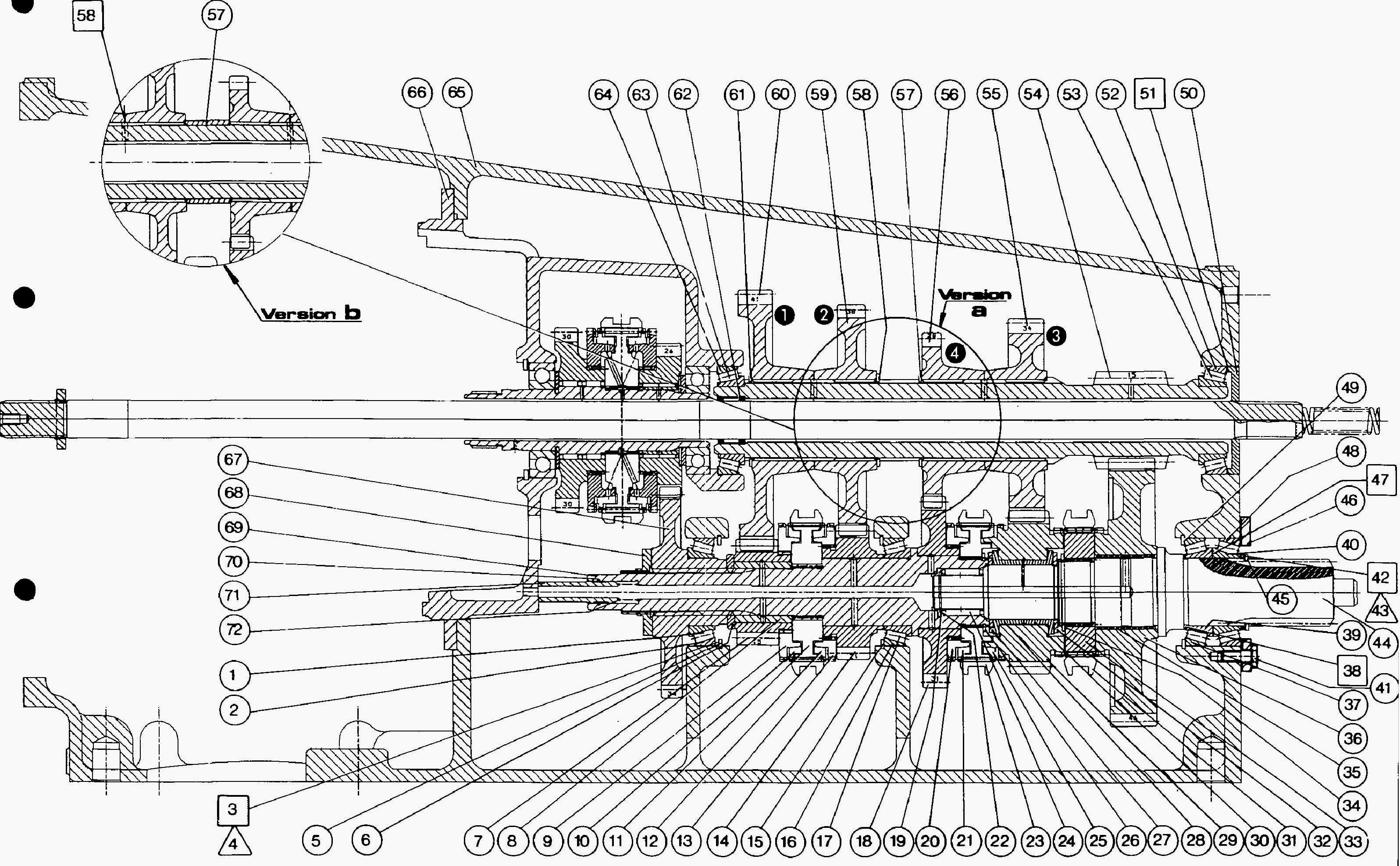
Fig.2
- Check that the hydraulic ports of the High/Low cylinder (10) are
unobstructed.
- Fit the cylinder (10) together with the «0» ring (11) in the housing.
- Position the High/Low fork (20) in the coupler.
- Fit the seals (12) and (14) on the piston (13) then insert it into the
cylinder bore.
- The setscrew holes should face the tapped holes in the fork.
Immobilize the fork with a setscrew (19).
- Clean and assemble the mechanical lock (22), the tapered bearing (23),
the cone (24) and castellated nut (21).
- Fit the 3rd and 4th speed gear forks (6), 1st and 2nd gears (5) and
the lock assembly (25).
- Insert the selector rail (7) through the rear of the housing and slide
it into the piston, the Jock assembly and the forks.
- For the MF 3070, 3050 Tractor 4x4 gearbox, do not forget the Al B fork
(4).
- Fit the bearing (15) and tighten the bolts (16) to a torque of 27-32
Nm.
- Clean the setscrew (8) with solvent, coat with Loctite 542 and tighten
to a torque of 28-43 Nm.
- Clean the insert (9). coat with Loctite 542 and press it in level with
the housing.
- Fit the locking plungers (3), the springs (2) and tighten the plugs
(1) to a torque of 50-70 Nm. Note: Gearbox fitted with creeper gears
(Fig.61).
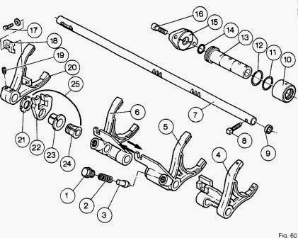
Fig.60
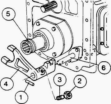
Fig.61
- Fit the sleeve (5), the fork (4) and the pin (1). Position the fork
and the locking plunger (3) on the flat of the shifter rail (6) (between
the two locking notches).
- Tighten the locking peg to compress the ball. Slacken the screw a
quarter turn. Clean the nut (2) with solvent and coat with Loctite 241.
- Tighten to a torque of 15-20 Nm. Check that the fork is correctly
locked. Setting the High/Low range fork.
- Principle: Positioning or the selector fork (20) on the rail is made
possible by the different centre to centre distances of the tapped holes
Y and of the notches Z on the
piston (13).
- The fork's position is altered by turning either the front screw or
the rear screw as necessary (Fig.62).
- Position the control piston (13) and the coupler (31) in the High
range.
- Keep the coupler in contact with the high range gear (29) (3rd gear on
the 4 x 2 gearbox - 4th gear on the 4 >; 4 box).
- Adjust the position of the fork (20) by turning the two adjusting
screws (19) after cleaning them with a solvent and lightly coating them
with Loctite 221 to obtain a play
of J1 s 0.3 mm between the rear face of the plate and the coupler.
- Use the locally made-up tool to carry out the adjustment.
- Position the control piston (13) and the coupler (31) in Low range.
- Check that there is a play of J2 = 0.3 minimum (value obtained by J1
adjustment) between the plate and the coupler with the latter in contact
with the Low range gear
(36) (Fig.65).
- Tighten the screws to a torque of 35 Nm without changing the
adjustment. Note: In Low range position, if the face X of the fork (20)
plate is in contact with the coupler
(Fig.65) increase the play J1.
- Move the fork into the Low range position.
- Slightly slacken the castellated nut (21). Lightly coat the thread of
the cone (24) with Loctite 270.
- Move the forks into the neutral position.
- Divide the J3 and J4 play (minimum 0.3 mm) equally so that the
mechanical lock (22) moves freely.
- Tighten the castellated nut (21) to a torque of 50 Nm using spanner
3615334 M01 and a spring balance.
- Coat the inner face of the slider (18) with Loctite 648 and the bolt
(17) with Loctite 241, Fit the washer and the bolt.
- Equalize the J5 and J6 clearances (minimum 0.3 mm) between the slider
and the lock in the High and Low range positions.
- Tighten the bolt to a torque oi 27-32 Nm.
- Check the operation of the High/Low range and of the lock.
- Check the operation of the gears and of the A/B range.
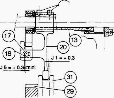
Fig.62
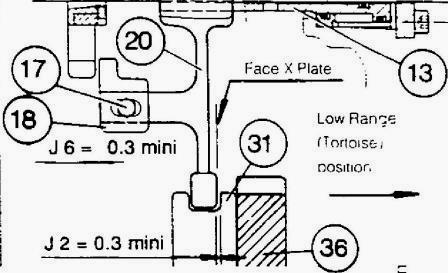
Fig.65
MF 3050, 3070 Gearbox Reverse shuttle selector - Adjustment:
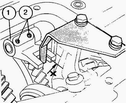
Fig.71
- Move the selector (1) into neutral.
- Fit and tighten service tool 3582434 M01 with two centring bolts
fitted with spacers.
- Coat the setscrews (2) with Loctite 221.
- Position face X of the reverse shuttle selector in contact with the
service tool using the screws (2).
- Tighten the screws to a torque of 35 Nm.
- Remove the tool.
Selector cover – Refitment MF 3050, 3070 Tractor 4x2 Gearbox:
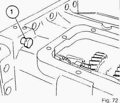
Fig.72
- Clean the mating face of the cover (56).
- Move the reverse shuttle selector into neutral. Engage 1st gear.
- Coat the mating face of the gearbox housing with a gasket sealant.
Note: Remember to position the bolt (1) on the housing (Fig. 72).
- Turn the two cover levers to the left, keeping them parallel.
- Lay the cover on the gearbox ensuring that the levers are correctly
positioned in the selectors (Fig.73).
- Carry out procedure 5 in reverse, Note: Tightening torque 50-70 Nm.
Check:
- the movement of all the gears and the position of the High/Low
(Hare/Tortoise) range,
- the operation of the reverse shuttle.
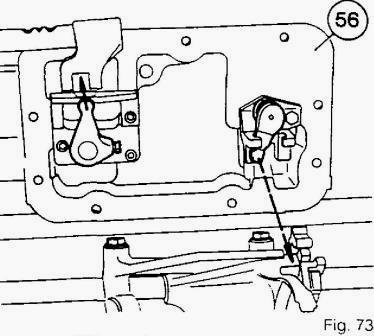
Fig.73
MF 3050, 3070 Tractor 4x4 Gearbox
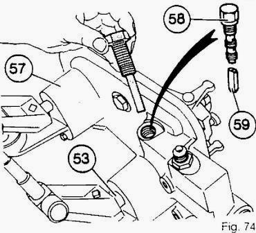
Fig.74
- Clean the mating face of the cover (57).
On the gearbox:
- Check that the reverse shuttle selector is in neutral and the A/B fork
in position B (forwards).
- Engage 1st gear.
On the cover:
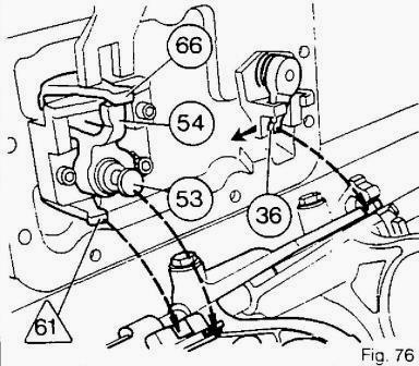
Fig.76
- Remove the pressure valve (58) and the plunger 59 (Fig. 74).
- Lock the control shaft (53) in position B with lugs (66) and (54)
lined up (Fig. 76) using tool 3615053 M01 (Fig.74) (tighten but not
fully).
- Move the lug 61 of the A/B fork into position B (forwards). Move the
gear lever to the left (into 1st) (36).
- Assemble the cover on the gearbox by engaging the lugs (54) and (66)
in the reverse shuttle selector and the lug 61 into the A/B fork, then
engage the lug (36) into
the 1st and 2nd gear fork and the mechanical lock (Fig.76).
- Position the cover. Fit the bolts and tighten to a torque of 50-70 Nm.
Remove tool 3615053 M01.
- For a gearbox fitted with creeper gears, fit the cable bracket (1)
(Fig. 77) To correctly centre the cover, first tighten bolt 3 (Fig.77).
Carry out a manual check, using
the levers, that the lugs have been correctly fitted into the selectors.
- Install the plunger 59 and the pressure valve (58) and tighten to a
torque of 18-20 Nm.
Check:
- the free movement of all gears
- the High/Low range positions
Adjust the A/B range.
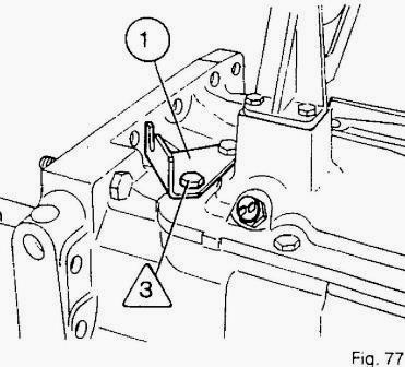
Fig.77
________________________________________________________________________________
________________________________________________________________________________________
 SPECS
SPECS LOADERS
 MAINTENANCE
 PROBLEMS
________________________________________________________________________________________
 MF 1523
 MF 1531
 MF 135
 MF 1547
 MF 1635
________________________________________________________________________________________
________________________________________________________________________________________
 231
231 231S
231S 235
235 240
240 241
241________________________________________________________________________________________
 255
255 265
265 274
274 285
285 375
375________________________________________________________________________________________
________________________________________________________________________________________
 916X Loader
 921X Loader
 926X Loader
 931X Loader
 936X Loader
________________________________________________________________________________________
 941X Loader
 946X Loader
 951X Loader
 956X Loader
 988 Loader
________________________________________________________________________________________
 1655
1655 GS1705
 1742
1742 2635
2635 4608
4608________________________________________________________________________________________
 1080
1080 1100
1100 2615
2615 3050
3050 3060
3060________________________________________________________________________________________
 4708
4708 5455
5455 5450
5450 5610
5610 5613
5613________________________________________________________________________________________
 DL95 Loader
 DL100 Loader
 DL120 Loader
 DL125 Loader
 DL130 Loader
________________________________________________________________________________________
 DL135 Loader
 DL250 Loader
 DL260 Loader
 L90 Loader
 L100 Loader
________________________________________________________________________________________
 6499
6499 7480
7480 7618
7618 7726
7726 1533
1533________________________________________________________________________________________
 2604H
2604H 2607H
2607H 4455
4455 4610M
4610M 4710
4710________________________________________________________________________________________
 L105E Loader
 L210 Loader
 1014 Loader
 1016 Loader
 1462 Loader
________________________________________________________________________________________
 1525 Loader
 1530 Loader
 232 Loader
 838 Loader
 848 Loader
________________________________________________________________________________________
 5712SL
 6713
6713 6715S
6715S 7475
7475 7615
7615________________________________________________________________________________________
 7716
7716 7724
7724 8240
8240 8650
8650 8732
8732________________________________________________________________________________________
 246 Loader
 1036 Loader
 1038 Loader
 1080 Loader
 856 Loader