________________________________________________________________________________
Massey Ferguson 3095, 3125 Tractor Gearbox – Speedshift
The speedshift unit is mounted at the front of the Massey Ferguson 3095,
3080, 3105, 3125 gearbox input. It is a hydraulically operated
gearchange device which provides two different input ratios to the main
gearbox.
It does this by means of:
- a multidisc hydraulic clutch,
- an epicylic gear train consisting of a planetary carrier with three
twin planetary gears, an input sun gear and an output sun gear,
- a system for braking the planetary carrier hydraulically. The design
of the speedshift allows the ratios to be changed on the move, even
under full load, without declutching.
Different versions
The following versions can be obtained as a function of the number of
teeth on sun gears 6 and 7 and the order in which they are fitted: 30
km/h or 40 km/h version/version with super creeper gears.
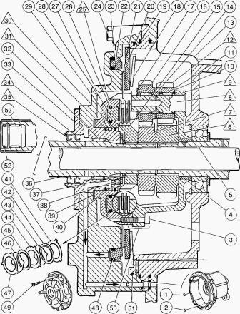
Fig. 3
30 Kph and super creeper version : stepdown 40 Kph version : stepup
(Fig. 3) - in this mode (Fig. 3), there is no supply to the hydraulic
components and the
speedshift operates as a purely mechanical transmission.
Oil in chamber of pistons (28) and (48) returns to the housing via the
gallery C and the solenoid. The drive from the hollow primary shaft (36)
is transmitted to the input
sun gear 7 by the splines which secure the gear to the shaft. Sun gear R
drives the compound planetary gears 12 which are mounted to rotate
freely on spindles 8.
The planetary gears in turn drive the output sun gear 6, which is
splined to the hollow secondary shaft (5). in one of the following
ratios: 30km/h 1.26 stepdown - 40km/h
1.26 stepup - super creeper 7.8 stepdown.
Since no hydraulic pressure is applied, the planetary carrier assembly
(50) is locked against rotation by a Belleville spring disc (18) which
applies pressure to pressure
plate (20) and thus stops disc (21) from turning, the latter being
locked to the planetary carrier assembly in rotation by splines.
Hydraulic operation - direct transmission
The range is changed by actuating the solenoid valve. which then feeds
hydraulic oil to the chambers behind pistons (48) and (28)
simultaneously.
Braking piston (48) is then applied to pressure plate (20), which
compresses the Belleville spring disc (18), thus releasing disc (21) and
the planetary carrier assembly
(50). At the same time clutch piston (28) clamps together pressure
plates (41), (44), (47) and the discs (42), (45) which are driven by hub
(15).
Since the pressure plates are secured to the planetary carrier by three
lugs, drive is transmitted from the primary input shaft (36) to the hub
(15) and from there to the
clutch assembly which transmits it to the planetary carrier (50).
The primary shaft (36) and the planetary gear and sun gear assembly turn
at the same speed as the secondary shaft (5) thus giving direct
transmission in the ratio of
1/1.
Front cover operations
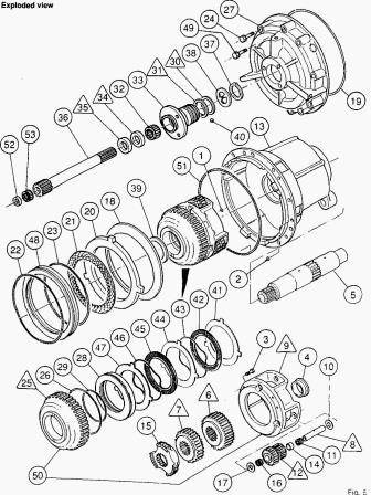
Fig.5
Removing the front cover tractors:
- Split the tractor between the engine and gearbox Massey Ferguson 3125
Tractor
- Split the tractor between the engine and gearbox.
- Remove the PTO shaft. Withdraw seal (52).
- Remove the bleed and supply pipes to the clutch assembly.
- Drain the gearbox only of oil. Unscrew bolts (24) (Fig.6).
- Screw two pilot pins into the gearbox housing in diametrically opposed
positions (Fig.6).
- Unscrew the three bolts (49) a little at a time, taking them in order
(Fig.6).
- Remove cover (27) together with shaft (36) (Fig.6). Discard O-rings
(1) and (2), (19) and (51).
- In anticipation of future rationalisation of the design of the
speedshift, the former 6-lugged friction disc has been replaced by one
with 40 internal splines.
- The hydraulic cover and the planetary carrier cover, and the bolts for
securing them, have also been replaced by new covers and bolts adapted
to the design with the
splined disc.
- Take out disc (21), pressure plate (20), Belleville spring disc (18)
and planetary carrier assembly (50).
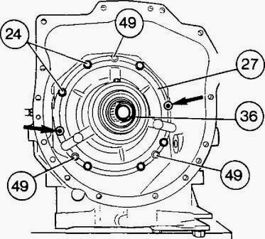
Fig.6
Disassembling the front cover:
- Extract circlip (37) and take out lug washer (38).
- Withdraw shaft (36) from the front of the cover.
- Take out needle-roller bearing (53).
- Remove washer (39).
Massey Ferguson 3095, 3050 Tractor:
- Take out the clutch slave cylinder assembly
- You are advised not to take the release bearing out of the slave
cylinder to avoid damage to the seals.
- Withdraw the release bearing from the slave cylinder for a distance of
approx. 40 mm, take off the bellows.
- Unscrew the three bolts holding the cylinder in place.
Massey Ferguson 3125, 3115 Tractor:
Take out the clutch stave cylinder assembly - Unscrew the bolts holding
me slave cylinder assembly in place and take the assembly out. Withdraw
piston (48) from
the cover.
All tractors:
- Remove seals (22) and (23) and discard them.
- MF 3095, 3125 tractors, new speedshift rings made of PTFE rather than
cast iron and with gaps increased to 2.1/2.4 mm were introduced as from
serial no.
N155012.
- Remove seal rings 30 and 31 (discard these rings).
- Remove lip seals 34 and 35 and discard them.
- Take out needle-roller bearing (32) and discard it.
- Drive ring carrier (33) out of cover (27) (Work from the rear of the
ring carrier using a plasticiaced mallet as a drift).
- Separating planetary carrier and cover assembly.
- Place the planetary carrier assembly (50) down on a bench (with the
planetary carrier cover 9 on top).
- Unscrew bolts (3).
- Separate planetary carrier cover 9 from hydraulic cover 25 while
holding sun gears 6 and 7 in position in planetary carrier cover
(Fig.9).
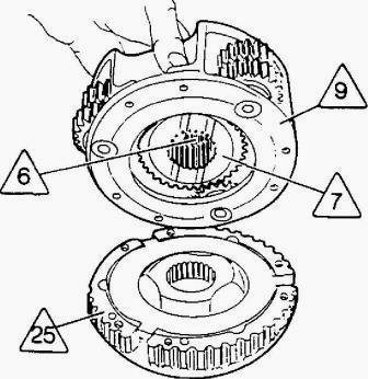
Fig.9
Disassembling planetary carrier assembly
Take out the 1st sun gear:
- H36 tooth in 30 km/h version
- (6) 30 tooth in 40 km/h version
- (7) 30 tooth in super creeper version - Mark the direction in which
the lubricating grooves in the sun gear should face when the gear is
refitted.
Drive out spindles 8 with a drift and a mallet.
Take out the planetary gears 12.
Take out needle-roller bearings (11) and (16). spacers (14), and washers
(10) and (17).
Take out the second sun gear:
- (6) 39 tooth in 30 km/h version (7) 36 tooth in 40 km/h version
- (6) 39 tooth in supper creeper version (Fig.2) . Bush (4) is a force
fit in planetary carrier cover 9.
Disassembling the hydraulic cover:
- Take out splined hub (15).
- Take out pressure plate (41), disc (42), spring washer (43). pressure
plate (44), disc (45), spring washer (46) and pressure plate (47).
- Withdraw piston (28) from cover 25.
- Remove O-rings (26) and (29) and discard them. In the supper creeper
version, cover 25 and piston (28) differ from those in the 30 and 40
km/h versions.
The cross-sectional area of the piston is greater and this means that
the diametric cutouts in the cover are larger.
Reassembling the planetary trier:
- Glean and check the parts and replace any which are faulty.
- Lubricate the needle-roller bearings. Check that the oilways in
spindles 8 are not blocked, m/h version
- Fit the 39 tooth sun gear 6 into the planetary carrier cover. km/h
version.
- Fit the 36 tooth sun gear 7 into the planetary carrier cover.
- Fit the tooth sun gear 6 into the planetary carrier cover.
- In all versions, fit the gear so that the lubricating grooves in it
are facing towards face F of the planetary carrier cover. Fit a
needle-roller bearing (11), a spacer (14)
and a needle-roller bearing (16) into a planetary gear 12V
Fit an assembled planetary gear into the cover, with the following gears
closer to face F in the respective cases:
- 21 tooth: 30 km/h version
- 18 tooth: 40 km/h version
- 27 tooth: super creeper version.
The planetary gear is marked with three punch marks made in a single
face. Each punch mark indicates two teeth which line up. Fit washers
(10) and (17).
Line up the planetary gear and washers with a locating rod made up
locally : diameter = 16 mm, length = 80 mm.
Insert spindle 8 into the unobstructed bore in face F and drive it home
with a mallet until it is slightly recessed below the face.
The oilway opening onto the circumference of spindle 8 must face
outwards. The oilway opening onto the end face of spindle 8 must face
towards face F of the
planetary carrier cover.
Repeat procedures to fit the other two planetary gears.
The marks (punch marks) on the three planetary gears must line up with
the centre on line spaced 120P apart. Once fitting of the spindles I8\
has been completed,
re-check that the marks on the planetary gears line up as above.
If the marks do not line up properly, this will cause damage to the
speedshift.
Fit the following sun gears in the respective versions :
- (7) 36 tooth: 30 km/h version
- (6) 39 tooth: 40 km/h version
- (7) 30 tooth: super creeper version
In all versions, fit the gear so that the lubricating grooves in it are
facing towards face F of the cover.
Reassembling the hydraulic cover:
- Clean and check the parts and replace any which are faulty.
- Make sure that the three openings into the 17 bar passage in the
hydraulic cover /2S\are not blocked.
- Lubricate O-rings (26) and (29) and fit them to piston (28).
- Lubricate the faces against which the piston seals bear in the
hydraulic cover.
- Place the piston in the cover with the grooves facing towards the
operator.
- Tap the piston (28) gradually home into the cover by working
progressively round its face with a plastic-faced mallet.
- Once the piston is fitted, check that no pieces have been detached
from the O-rings.
- Refit the splined hub (15) making sure it is correctly orientated.
- Refit pressure plate (47), spring washer (46), disc (45), pressure
plate (44), spring washer (43), disc (42) and pressure plate (41).
- Place the gaps in spring washers (43) and (46) in diametrically
opposed positions.
Reassembling the planetary carrier assembly:
- Screw two pilot pins into the hydraulic cover 25 in diametrically
opposed positions.
- Fit the planetary carrier cover 9 to the hydraulic cover 25, while
holding the sun gears 6 and 7 in position.
- Position the two covers so that the balancing marks (milled grooves or
paint lines) are as far away from each other as possible.
- Refit bolts (3). Bolts must be tightened to a torque of 10-14 Nm.
- Tap spindles 8 in with a pin punch so that they butt against the
hydraulic cover 25V
- Check: that discs (42) and (45) are not compressed / that planetary
gears 12 and sun gears 6 and 7 can turn freely.
- Fit planetary carrier assembly (50) to shaft (5).
- Fit Belleville spring disc (18).
- Fit pressure plate (20) into housing (13).
- Apply three spots of grease («Amber Technical" or equivalent) to the
lugs on the pressure plate.
- Engage friction disc (21) onto the planetary carrier assembly.
Reassembling the front cover:
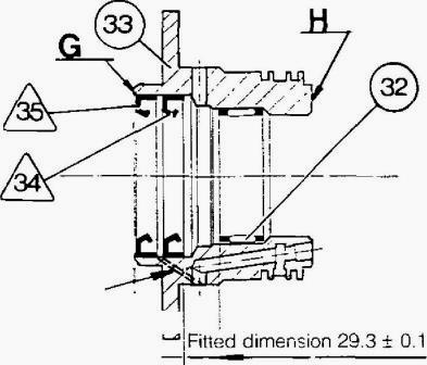
Fig.20
- Clean the mating face and the rest of the cover. Make sure that the 17
bar passage and the lubricating passage are not blocked.
- Fit seals (22) and (23) to piston (48).
- Lubricate the surfaces in the speedshift cover against which the
piston seals bear.
- Position the piston on the cover with its grooves facing towards the
operator.
- Tap piston (48) gradually home into the cover by working progressively
round its face with a plastic-faced mallet.
- Once the piston is fitted, check that no pieces have been detached
from the O-rings.
- Clean the ring carrier and its mating face (check that the 17 bar
passage and the lubricating pas-sage are not blocked). Ball (40) is
crimped into the ring carrier.
Position (Fig.20) :
- needle-roller bearing (32) at 29.3 ± 0.1 mm from faceG - seal 34 at
43.8 mm from face H
- wide seal 35 at 0.3 - 0.8 from face G.
Use a press and a suitable press tool to position the bearing and seals
perpendicular to the axis of the ring carrier.
- Having fitted seals 34 and /35, check that the two pressure-relief
passages are not blocked.
- Apply a gasketing compound (Loctite Masterjoint 510 or equivalent) to
the mating face of the cover to allow the ring carrier (33) to be
fitted.
- Screw two pilot pins (1) into the cover. Engage the ring carrier in
the cover bore.
- Check that the openings of the 17 bar passage and the lubricating
passage in the ring carrier match up with the passages in the cover.
- Tap the ring carrier home in the cover. Lubricate seals 34 and 35V
MF 3095 Tractor:
- Refit the clutch slave cylinder assembly.
- Apply Loctite 241 to the three bolts and tighten them to torques of: 8
mm;25 - 35 Nm / 50 - 70 Nm.
- Refit the bellows and push in the release bearing.
- Refit the clutch slave cylinder assembly.
- Apply Loctite 241 to the bolts which hold the clutch slave cylinder
assembly in place and tighten them to the following torques : 8 mm;25-35
Nm 10 mm/50 - 70 Nm.
MF 3095, 3125 tractors:
- Fit needle-roller bearing (1) so that it is 15-16 mm from the front
face of the shaft.
- Lubricate shaft (36) and insert it in ring carrier (33) from the
front.
- Make sure that the lubricating passages in the shaft are not blocked.
- Cover the splines in the shaft temporarily to avoid damage to seals 34
and 35.
- Refit washer (38) and circlip (37).
- Refit rings 30 and 31 and make sure that they turn freely in the
grooves.
- Having made this check, remove the rings, preform them by reducing
them to approximately 1 /3 of their original diameter, and coat them
with miscible grease
(Amber Technical or equivalent) to ensure that they will be held in
position effectively when the front cover is being refitted.
- Fit the rings into their respective grooves, making sure that : they
do not project from the circumference of the ring carrier, their ends
are correctly overlapped.
- Even the slightest damage to the rings may give rise to leaks followed
by pressure dropping in operation.
- Grease washer (39) and fit it into cover (27).
- Fit new O-rings (1) and (2), (19) and (51).
- Check that the locating pin is present in the reversing mechanism
housing and that the two pilot pins are fitted.
Refitting the front cover:
- Fit front cover (27) together with shaft (36).
- Use the PTO shaft to make mating-up easier (only when fitting on
tractor).
- Check that the 17 bar and lubricating passages in the cover match up
with the openings in the housing.
- Refit bolts (24) and tighten them to a torque of 45 - 60 Nm.
- Fit bolts (49) and tighten them to a torque of 25 -35 Nm.
- Reconnect the supply and bleed pipes to the clutch slave cylinder
assembly.
- Re-unite the tractor between engine and gearbox.
Massey Ferguson 3125 tractors:
- Top up the oil in the housing,
- Bleed the clutch circuit.
- Carry out a road test on the speedshift control.
________________________________________________________________________________
 SPECS
SPECS LOADERS
 MAINTENANCE
 PROBLEMS
________________________________________________________________________________________
 MF 1523
 MF 1531
 MF 135
 MF 1547
 MF 1635
________________________________________________________________________________________
 231
231 231S
231S 235
235 240
240 241
241________________________________________________________________________________________
 255
255 265
265 274
274 285
285 375
375________________________________________________________________________________________
________________________________________________________________________________________
 916X Loader
 921X Loader
 926X Loader
 931X Loader
 936X Loader
________________________________________________________________________________________
 941X Loader
 946X Loader
 951X Loader
 956X Loader
 988 Loader
________________________________________________________________________________________
 1655
1655 GS1705
 1742
1742 2635
2635 4608
4608________________________________________________________________________________________
 1080
1080 1100
1100 2615
2615 3050
3050 3060
3060________________________________________________________________________________________
 4708
4708 5455
5455 5450
5450 5610
5610 5613
5613________________________________________________________________________________________
 DL95 Loader
 DL100 Loader
 DL120 Loader
 DL125 Loader
 DL130 Loader
________________________________________________________________________________________
 DL135 Loader
 DL250 Loader
 DL260 Loader
 L90 Loader
 L100 Loader
________________________________________________________________________________________
 6499
6499 7480
7480 7618
7618 7726
7726 1533
1533________________________________________________________________________________________
 2604H
2604H 2607H
2607H 4455
4455 4610M
4610M 4710
4710________________________________________________________________________________________
 L105E Loader
 L210 Loader
 1014 Loader
 1016 Loader
 1462 Loader
________________________________________________________________________________________
 1525 Loader
 1530 Loader
 232 Loader
 838 Loader
 848 Loader
________________________________________________________________________________________
 5712SL
 6713
6713 6715S
6715S 7475
7475 7615
7615________________________________________________________________________________________
 7716
7716 7724
7724 8240
8240 8650
8650 8732
8732________________________________________________________________________________________
 246 Loader
 1036 Loader
 1038 Loader
 1080 Loader
 856 Loader