
________________________________________________________________________________
Massey Ferguson 6480, 6475, 6485, 6255 Tractor Hydraulic system - Right-hand cover plate
The Massey Ferguson 6480, 6475, 6485, 6255 tractor right-hand cover
plate is fitted on the intermediate housing (GPA30 rear axle) or the
centre housing (GPA20 and GPA40 rear axles). It is the main support for
a number of components.
It incorporates the various channels for the charge system, the
lubrication system and the low flow rate and high flow rate systems of
the 110 l/min or 150 l/min Load Sensing system.

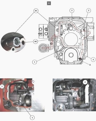
On its internal face, the cover contains:
- the variable displacement pump (41) with a capacity of 45
cm3/revolution (GPA20, GPA30 and GPA 40 rear axles) (110 l/min Load
Sensing hydraulic system) or the variable displacement pump (41) with a
capacity of 60 cm3/revolution (GPA 40) 150 l/min Load Sensing hydraulic
system.
- its drive gear (39) fitted to the MF 6480, 6475, 6485, 6255 variable
displacement pump
- the safety valve (45) of the low pressure system set to 24 bar,
- the safety valve (44) of the charge and lubrication system set to 5
bar. This safety valve differs depending on the tractor's Load Sensing
hydraulic equipment (110 l/min or 150 l/min).
On its external face, the cover contains:
- the main filter 15 μ (27); this differs depending on the Massey
Ferguson 6480, 6475, 6485, 6255 tractor's Load Sensing hydraulic
equipment (110 l/min or 150 l/min).
- one or two priority blocks serving different functions of the low and
high flow rate systems.
For the 40 kph version with trailer braking, the Massey Ferguson 6480,
6475, 6485, 6255 tractors are fitted with a hydraulic unit with two
priority blocks.
For the 50 kph version with or without trailer braking, the tractors are
systematically fitted with a hydraulic unit with two priority blocks.
These priority blocks can be distinguished from the priority blocks on
the 40 kph version with trailer braking by a higher number of hydraulic
ports.
These additional hydraulic ports are used by the high-pressure braking
unit;
- the pressure relief-valve (2);
- the Massey Ferguson 6480, 6475, 6485, 6255 variable displacement pump
hydraulic regulator (12);
- the three or four flanged solenoid valves (2 or 4WD) that control the
low pressure functions (17 or 21 bar);
- diagnostics connectors for high and low pressure (11) (20),
lubrication charge (29), LS (9);
- the engine speed sensor (25) (if fitted);
- the low pressure (14) and charge (42) switches as well as the main
filter blockage indicator (34).
Description
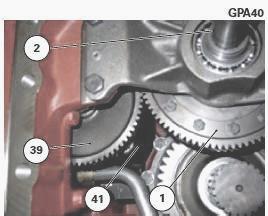
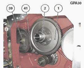
The engine movement transmitted to the gear (1) via the shaft (2) drives
the gear (39) of the variable displacement pump (41). The shaft (2) is
splined to the engine flywheel vibration damper via the PTO shaft.
The oil coming from the charge pump located on the left-hand cover plate
(see chapter 9) is directed towards the priority block via the pipe (3)
(GPA20 and GPA40) or the pipe (54) (GPA30) via the variable displacement
pump (41), to supply the required function.
The pipe (1) (GPA20 and GPA40 rear axles) or the pipe (55) (GPA30 rear
axle) carries the oil coming from the 5 bar safety valve (44) to the
suction manifold (4) fitted on the left-hand cover plate.
MF 6460, 6455, 6445, 6265 GPA20 and
GPA40 rear axles assemblies
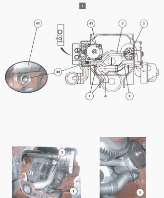
GPA20 LS 110 l/min
GPA40 LS 110 l/min
GPA40 LS 150 l/min
Parts list
(1) Continuity pipe from safety valve, (2) Charge pump, (3) Charge pipe,
(4) Suction manifold, (41) Variable displacement pump, (44) 5 bar safety
valve
Legend
A Source of suction
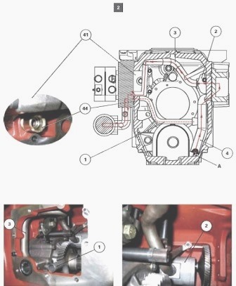
MF 6480, 6475, 6485, 6255 tractor
GPA30 rear axle assembly
GPA30 LS110 l/min
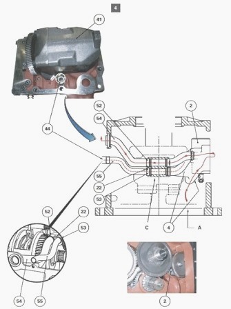
Parts list
(2) Charge pump, (4) Suction manifold, (22) Mecanindus pin, (41)
Variable displacement pump, (44) 5 bar safety valve, (52) "O" ring, (53)
"O" ring, (54) Charge pipe, (55) Continuity pipe linked to the 5 bar
valve
Legend
A - Source of suction
C - Compartment
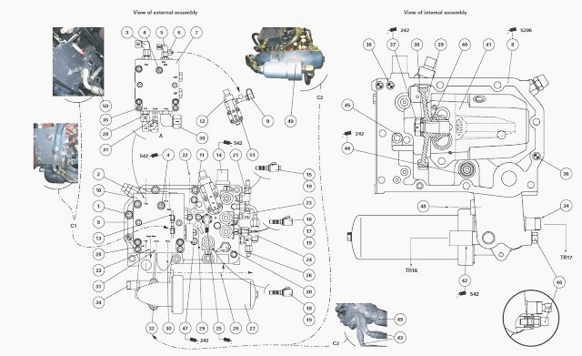
Parts list
(1) Screw, (2) High-pressure (HP) relief valve, (3) Supply to the
Orbitrol spool valve, (4) Screw, (5) LS pilot flow from the Orbitrol
spool valve, (6) LS pilot flow to the variable displacement pump
hydraulic regulator, (7) Single priority block (40 kph tractors without
trailer braking), (8) Hydraulic cover plate, (9) LS diagnostics
connector,
(10) Hydraulic unit with two priority blocks (40 kph Massey Ferguson
6460, 6455, 6445, 6265 tractors with trailer braking) (if fitted), (11)
High-pressure (HP) diagnostics connector, (12) Pump hydraulic regulator,
(13) Trailer brake unit vent line, (14) Low pressure (BP) switch (17 or
21 bar), (15) to (18) Solenoid valves (PTO, PTO brake, front and rear
differential lock, 4WD (if fitted)), (19) Flanges, (20) Low-pressure
(BP) diagnostics connector (17 or 21 bar), (21) PTO pipe, (22) Trailer
brake control from brake master cylinders (40 kph tractors) or
block/valve assembly (tractors fitted with high-pressure braking), (23)
PTO brake pipes, (24) 2WD or 4WD differential lock pipes, (25) Engine
speed sensor (if fitted), (26) 4WD pipes, (27) Main filter (15 μ), (28)
Hydraulic line (17 or 21 bar), (29) Lubrication and charge pressure
diagnostics connector, (30) Supply to the linkage valve and auxiliary
spool valves, (31) LS pilot flow from auxiliary spool valves and linkage
valve, (32) Screw, (33) Hydraulic line supply to trailer brake rear
coupler, (34) Blockage indicator (there are two types of fitting,
depending on tractor serial number), (35) Screw, (36) Locating pins,
(37) Nut, (38) Washer, (39) Gear, (40) Key, (41) Variable displacement
pump, (42) Lubrication and charge pressure switch, (43) Hydraulic lines
(running to and from the cooler), (44) 5 bar safety valve, (45) 22 or 24
bar safety valve, (46) Temperature switch or plug and "O" ring (there
are two types of fitting depending on tractor serial number), (47)
Variable displacement pump screw, (48) Hydraulic lubrication line, (49)
60 micron filter element, (50) Charge hose (GTA1040), (51) Screw
Legend
A - Single priority block (40 kph tractors without trailer braking)
TR16 Connector
TR17 Connector
In addition to the assembly views, the figure also shows hydraulic
components C1, C2 or C3, which may be fitted on or around the LS
right-hand hydraulic cover plate depending on the Massey Ferguson 6480,
6475, 6485, 6255 tractor hydraulic update level and the type of rear
axle (GPA20, GPA30 or GPA40).
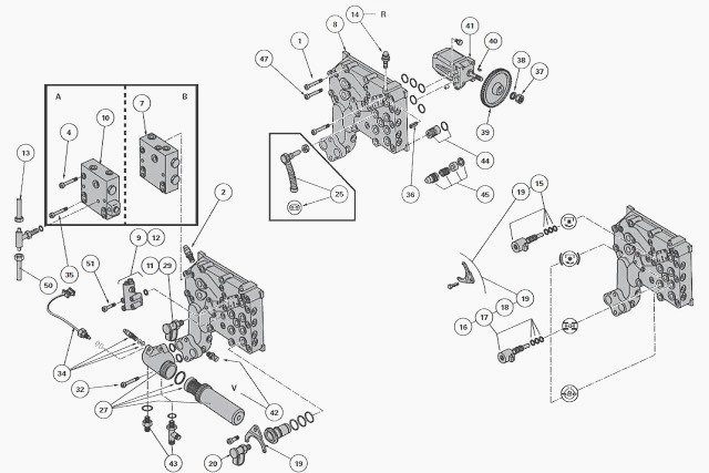
Identification of channels and ports on the
hydraulic regulator (12)
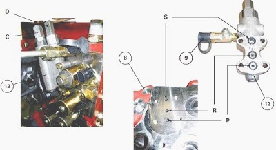
C - 22 bar adjustment screw
D - 200 bar adjustment screw
P - High pressure (HP) from variable displacement pump
R - To variable displacement pump control piston
S - Hydraulic regulator return
(8) - MF 6460, 6455, 6445, 6265 Hydraulic cover plate
(9) - LS diagnostics connector
Screws C and D are factory set. Do not modify these settings.
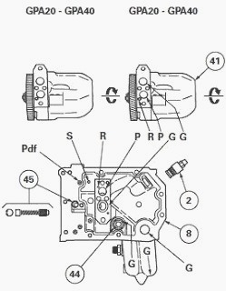
On the hydraulic cover plate (8) and the variable displacement pump (41)
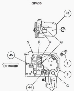
F - To main filter (15 μ)
G - Charge line
L - Lubrication line
P - High pressure (HP) outlet from variable displacement pump
PTO supply line (GPA20 and GPA40)
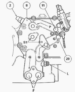
R - Line to variable displacement pump control piston
S - Hydraulic regulator return line
S1 - Priority block(s) return line (depending on version)
(2) 230 bar high-pressure (HP) relief valve, (11) High pressure
diagnostics connector, (29) Lubrication and charge pressure diagnostics
connector, (44) 5 bar safety
valve, (45) 22 or 24 bar safety valve
________________________________________________________________________________
________________________________________________________________________________________
 SPECS
SPECS LOADERS
 MAINTENANCE
 PROBLEMS
________________________________________________________________________________________
 MF 1523
 MF 1531
 MF 135
 MF 1547
 MF 1635
________________________________________________________________________________________
________________________________________________________________________________________
 231
231 231S
231S 235
235 240
240 241
241________________________________________________________________________________________
 255
255 265
265 274
274 285
285 375
375________________________________________________________________________________________
________________________________________________________________________________________
 916X Loader
 921X Loader
 926X Loader
 931X Loader
 936X Loader
________________________________________________________________________________________
 941X Loader
 946X Loader
 951X Loader
 956X Loader
 988 Loader
________________________________________________________________________________________
 1655
1655 GS1705
 1742
1742 2635
2635 4608
4608________________________________________________________________________________________
 1080
1080 1100
1100 2615
2615 3050
3050 3060
3060________________________________________________________________________________________
 4708
4708 5455
5455 5450
5450 5610
5610 5613
5613________________________________________________________________________________________
 DL95 Loader
 DL100 Loader
 DL120 Loader
 DL125 Loader
 DL130 Loader
________________________________________________________________________________________
 DL135 Loader
 DL250 Loader
 DL260 Loader
 L90 Loader
 L100 Loader
________________________________________________________________________________________
 6499
6499 7480
7480 7618
7618 7726
7726 1533
1533________________________________________________________________________________________
 2604H
2604H 2607H
2607H 4455
4455 4610M
4610M 4710
4710________________________________________________________________________________________
 L105E Loader
 L210 Loader
 1014 Loader
 1016 Loader
 1462 Loader
________________________________________________________________________________________
 1525 Loader
 1530 Loader
 232 Loader
 838 Loader
 848 Loader
________________________________________________________________________________________
 5712SL
 6713
6713 6715S
6715S 7475
7475 7615
7615________________________________________________________________________________________
 7716
7716 7724
7724 8240
8240 8650
8650 8732
8732________________________________________________________________________________________
 246 Loader
 1036 Loader
 1038 Loader
 1080 Loader
 856 Loader