
________________________________________________________________________________
Massey Ferguson 6290, 6270, 6490, 6280 tractor variable displacement hydraulic pump
Variable displacement hydraulic pump
description
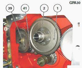
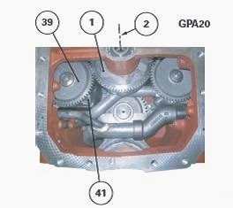
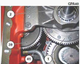
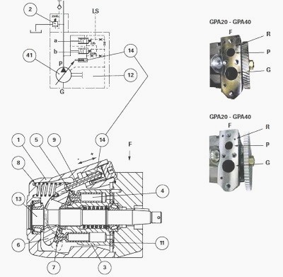
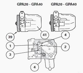
The variable displacement hydraulic pump (41)
Installed inside the Massey Ferguson 6290, 6270, 6490, 6280 right-hand
cover plate is driven by:
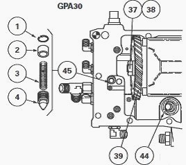
- the gears (1) and (39) (GPA30 rear axle);
- the Massey Ferguson 6290, 6270, 6490, 6280 tractor PTO clutch housing
teeth (1) (GPA20 and GPA40 rear axles). The helical teeth of the gear
(39) (GPA20 and GPA40) and its connected gear is replaced by spur cut
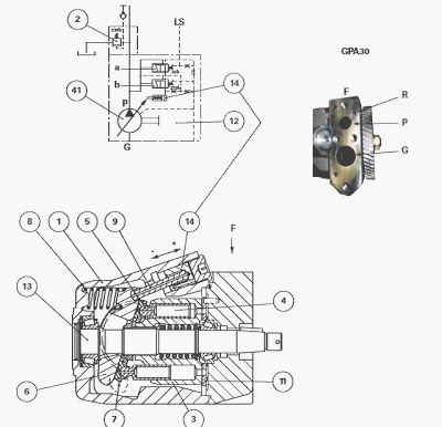
teeth. It comprises a body (1) and a cylinder (3) driven by the shaft
(13).
The cylinder contains nine axial pistons (4) thrust against ball joints
(5) in contact with plate (6) via the pads (7).
The angle of the plate is obtained by the equilibrium between the spring
(8), the pushrod (9) and the piston (14) controlled by a hydraulic
regulator receiving the Load
Sending (LS) pilot flow pressure from the high pressure (HP) components
via the single priority block or the hydraulic unit with two priority
blocks.
Depending on the angle of the plate, the length of travel of the axial
pistons (4) is modified, thus permitting the flow rate to adapt to the
operating conditions. The distribution plate (11) at the rear of the
cylinder, places the piston chambers in communication with the suction
ports and the pump delivery.
The ball joints (5) are drilled to provide lubrication between the pads
(7) and plate (6). The oil is then sent to the housing via port O.
The pressure relief valve is screwed into the upper left of the
right-hand hydraulic cover plate. The hydraulic regulator is fitted with
a diagnostics connector (Load Sending signal).
This is linked to the variable displacement pump (41) via the ports
drilled in the right-hand hydraulic cover plate. The diagnostics
connector is used to control the high pressure at the MF 6465, 6470,
6499, 6495 variable displacement hydraulic pump outlet.
Operation
Standby position
When the engine stops, the spring (8) automatically places the pump in
its maximum flow rate position.
When the engine is started, all ports are closed, and in theory no flow
is required. The pressure increases in line P. When it reaches 22 bar,
it pushes the hydraulic regulator spool "a" and connects with port R.
The pressure acts on the piston (14) and the pushrod (9) of the pump,
which moves the plate (6) into zero flow rate position. In practice, a
weak 3 to 5 bar flow rate remains in the MF 6290, 6270, 6490, 6280
tractor steering system, increasing the standby pressure to 28 bar.
Working position
When a function is activated (e.g.: an auxiliary spool valve), the 22
bar standby pressure drops as the system is opened. The 22 bar spring
restores the hydraulic regulator spool "a" to its initial position. The
piston (14) is linked to the return via S and R.
The spring (8) returns the pump plate (6) to full flow rate. The flow
rate from the pump creates the LS (load sending) pressure required to
activate the function.
The LS function then created balances the piston between, on the one
hand, the LS pressure plus the 22 bar pressure of the spring and, on the
other hand, the pump output pressure P.
As long as the spool "a" has not been balanced and is not maintained by
the pump supply, the piston (14) remains connected to the return and the
pump plate (6) at full flow rate (pump pressure P = LS pressure + 22
bar).
The closed centre system varies the pressure and flow rate in the
hydraulic system. Pump delivery pressure = XLS use pressure + standby
pressure (22 bar).
Sufficient flow rate, determined by the inner section of the Massey
Ferguson 6465, 6470, 6499, 6495 spool valve, is supplied by the pump to
maintain the pressure difference at the spool valve terminals (22 bar).
Parts list
G - From charge pump
P - High pressure (HP) outlet to single priority block or hydraulic unit
with two priority blocks
R - To control piston (14)
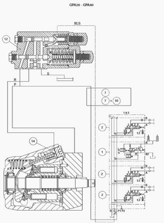
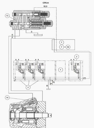
Parts list
(1) Linkage spool valve, (2) Auxiliary spool valves, (7) or [(7) and
(10)] Single priority block or hydraulic unit with two priority blocks
with or without trailer braking, (12) Variable displacement pump
hydraulic regulator, (14) Piston
Maximum position - zero flow rate
When the pressure at port P reaches 200 bar, spool "b" is pushed
forwards compressing its spring. The ports P and R are placed in
communication and piston (14) is brought to the zero flow rate position.
The hydraulic regulator (12), Installed on the hydraulic cover plate (8)
regulates the variable displacement pump pressure and flow rate
according to information transmitted by the LS signal. Screws C and D
are factory set. Do not modify these settings.
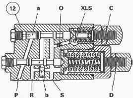
Legend
C - 22 bar adjustment screw
D - 200 bar adjustment screw
O - Decompression port
P - Variable displacement pump pressure
R - To piston (14)
S - Return
XLS Signal
Pressure relief-valve (2)
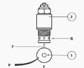
The high pressure flow delivered by the variable displacement pump
passes through channel P in the hydraulic cover plate and is directed
towards the single priority block or to the hydraulic unit with two
priority blocks (depending on version).
The pressure relief valve (2) set to 230 bar ± 5 and screwed into the
hydraulic cover plate, ensures the safety of the high pressure (HP)
system.
In case of any abnormal increase in pressure, valve (1) raises and the
oil is directed to the housing via ports R in the relief valve.
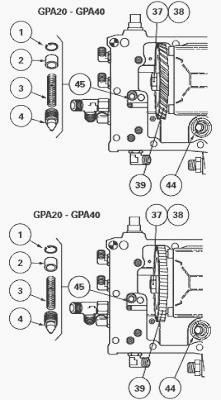
Removing and install the variable
displacement hydraulic pump
Remove the Massey Ferguson 6290, 6270, 6490, 6280 tractor right-hand
hydraulic cover plate.
Immobilise the driven gear (39) of the variable displacement pump (41)
by inserting a bronze drift between this gear and the hydraulic cover
plate. Release and slightly loosen the nut (37).
Unscrew the screws that secure the variable displacement pump to the
hydraulic cover plate. Separate the pump from the cover plate.
Place the variable displacement pump (41) on a workbench. Completely
unscrew the nut (37). Recover the washer (38).
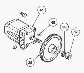
Using a suitable extractor, release and remove the driven gear (39) from
the tapered section of the shaft. Recover the key (40).
If necessary, remove the safety valve (45) from the Massey Ferguson
6465, 6470, 6499, 6495 low pressure system.
Reinstall
Clean the components. Replace those that are defective. Check that none
of the hydraulic cover plate channels are obstructed. Check the presence
of dowels (4). Replace the "O" rings (1) to (3).
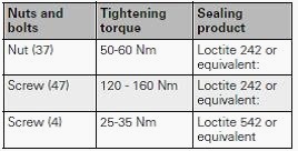
Repeat the pump removal operations in reverse order. Inside the cover
plate, apply a small bead of Loctite 574 or equivalent around the holes
of screws (47) to seal these holes.
Apply the same method as used with the left-hand cover plate. Lightly
smear the thread of the engine speed sensor (25) (if fitted) with
Loctite 5922 or equivalent. Adjust the sensor.
Adjusting the MF 6290, 6270, 6490,
6280 engine speed sensor
Depending on the type of transmission, the LS right-hand hydraulic cover
plate (8) may or may not be fitted with an engine speed sensor. If a
sensor is fitted, adjust it by carrying out the following steps.
Manually tighten the sensor (25) home, without forcing it, until it
comes into contact with the teeth of the driven gear (39) of the
variable displacement pump.
Loosen the sensor by a ½ to ¾ turn to obtain approximately 1 mm
clearance between the sensor and the driven gear. Tighten the nut to 5-7
Nm without turning the sensor.
________________________________________________________________________________
________________________________________________________________________________________
 SPECS
SPECS LOADERS
 MAINTENANCE
 PROBLEMS
________________________________________________________________________________________
 MF 1523
 MF 1531
 MF 135
 MF 1547
 MF 1635
________________________________________________________________________________________
________________________________________________________________________________________
 231
231 231S
231S 235
235 240
240 241
241________________________________________________________________________________________
 255
255 265
265 274
274 285
285 375
375________________________________________________________________________________________
________________________________________________________________________________________
 916X Loader
 921X Loader
 926X Loader
 931X Loader
 936X Loader
________________________________________________________________________________________
 941X Loader
 946X Loader
 951X Loader
 956X Loader
 988 Loader
________________________________________________________________________________________
 1655
1655 GS1705
 1742
1742 2635
2635 4608
4608________________________________________________________________________________________
 1080
1080 1100
1100 2615
2615 3050
3050 3060
3060________________________________________________________________________________________
 4708
4708 5455
5455 5450
5450 5610
5610 5613
5613________________________________________________________________________________________
 DL95 Loader
 DL100 Loader
 DL120 Loader
 DL125 Loader
 DL130 Loader
________________________________________________________________________________________
 DL135 Loader
 DL250 Loader
 DL260 Loader
 L90 Loader
 L100 Loader
________________________________________________________________________________________
 6499
6499 7480
7480 7618
7618 7726
7726 1533
1533________________________________________________________________________________________
 2604H
2604H 2607H
2607H 4455
4455 4610M
4610M 4710
4710________________________________________________________________________________________
 L105E Loader
 L210 Loader
 1014 Loader
 1016 Loader
 1462 Loader
________________________________________________________________________________________
 1525 Loader
 1530 Loader
 232 Loader
 838 Loader
 848 Loader
________________________________________________________________________________________
 5712SL
 6713
6713 6715S
6715S 7475
7475 7615
7615________________________________________________________________________________________
 7716
7716 7724
7724 8240
8240 8650
8650 8732
8732________________________________________________________________________________________
 246 Loader
 1036 Loader
 1038 Loader
 1080 Loader
 856 Loader