
________________________________________________________________________________
Kubota B1550, B6100, B6200 - Engine Service
B1550, B6200 tractors are equipped with a Kubota D850 3-Cylinder Diesel
Engine. B6100 tractor is powered by D650 model.
Kubota B1550, B6100, B6200 Engine - Checking
and Adjusting
Compression Pressure
After warming up the engine, stop it and remove the air cleaner, the
muffler and all nozzle holders. Install a compression tester for diesel
engines to nozzle holder hole. After making sure that the speed control
lever is set at the stop position (Non-injection), run the engine at 200
to 300 rpm with the starter. Read the maximum pressure. Measure the
pressure more than twice. If the measurement is below the allowable
limit, check the cylinder, piston ring, top clearance, valve and
cylinder head. Variances in cylinder compression values should be under
10%.
Top Clearance
Remove the nozzle holder. Lower the piston in the cylinder. Insert a
high quality fuse from the nozzle holder hole on the piston except where
it faces the valve or the combustion chamber insert. Rotate the flywheel
until the piston is raised and lowered again. Take out the fuse
carefully. Repeat three times with a new fuse in the other directions.
Measure the thickness of the crushed fuse with vernier calipers. If the
measurement is not within the factory specifications, check the oil
clearance of the crank pin and clearance between the piston pin and
bushing. Head gasket thickness (after retightened) - 1.05 to 1.15 mm
(0.0413 to 0.0453 in). Protection - 0.25 to 0.55 mm (0.010 to 0.022 in).
Draining Cooling Water and Engine Oil
Never remove radiator cap until cooling water temperature is below its
boiling point. Then loosen cap slightly to the stop to relieve any
excess pressure before removing cap completely. Prepare a bucket. Open
the drain cock to drain cooling water. Prepare an oil pan. Remove the
drain plug to drain engine oil in the pan.
Air Cleaner and Muffler
Remove the air cleaner. Remove muffler retaining nuts to remove the
muffler. Install the muffler gasket so that its steel side face the
muffler.
Checking Engine Oil Level
Level the engine. To check the oil level, draw out the dipstick, wipe it
clean, reinsert it, and draw it out again. Check to see that the oil
level lies between the two notches. If the level is too low, add new oil
to the specified level. When checking the oil level, make sure a Kubota
B1550, B6100, B6200 tractor is on a flat surface. It is impossible to
check accurately if the tractor is not level. Check the oil level before
starting or more than 3 minutes after the engine has stopped. At other
times, the check will not be accurate as oil stagnates in certain engine
parts. When using an oil of different maker or viscosity from the
previous one, drain old oil. Never mix two different types of oil.
Kubota B1550, B6100, B6200 - Engine Oil
Changing
After warming up, stop the Kubota D850/D650 engine. To change the used
oil, remove the drain plug at the bottom of the engine and drain off the
oil completely. Reinstall the drain plug. Fill the new oil up to the
upper notch on the dipstick. Change the type of engine oil according to
the ambient temperature. Above 25C - SAE 30 or 10W-30, 0C to 25C - SAE
20 or 10W-30, Below 0C - SAE 10W or 10W-30.
Changing Engine Oil Filter Cartridge
Remove the oil filter cartridge with a filter wrench. Apply engine oil
to the rubber gasket on the new cartridge. Screw the new cartridge in by
hand. Over-tightening may cause deformation of rubber gasket. After
cartridge has been replaced, engine oil normally decreases a little.
Check the oil level and add new oil to the specified level.
Fuel Filter Cleaning
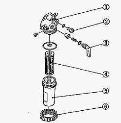
Water and grit present in the fuel will be extracted by the fuel filter.
When the filter is blocked/full, turn off the fuel tap, remove and clean
the filter. Air must always be removed when refitting the filter as
follows: Turn the fuel filter to the ON position. Open the taps as
follows - At the top of the injection pump. At the top of the fitter.
Half fill the tank. Turn the filter tap off. Fill the tank up to the
top. Run the engine for one minute then stop it. Turn off the pump tap.
Only open the pump tap and filter tap when draining.
Air Filter Cleaning
The air filter protects the engine from damaging dust and sand. It must
therefore be cleaned regularly to avoid engine seizure. Clean out the
dust from the filter cowling. Clean out the dust from the filter. When
installing the filter cowling, check that the "top" sign is well at the
top. The filter housing will otherwise leak air and particles will
damage the filter.
Kubota B1550, B6100, B6200 Engine -
Disassembly and Assembly
Cylinder Head Cover and Injection Pipe
Remove the cylinder head cover cap nuts. Remove the cylinder head cover.
Check to see that the cylinder head cover gasket is not defective.
Loosen the pipe damps. Remove the injection pipes.
Nozzle Holder Assembly
Remove the fuel overflow pipes. Loosen the lock nuts, and remove the
nozzle holder assemblies with a nozzle holder socket wrench. Remove the
copper gaskets on the seats.
Alternator and Fan Belt
Remove the alternator. Remove the fan belt. Check to see that there are
no cracks on the belt surface. After reassembling the fan belt, be sure
to adjust the fan belt tension.
Cylinder Head
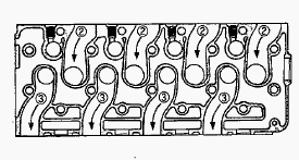
Loosen the pipe band, and remove the water return pipe. Remove the
cylinder head screws and nuts in the order, and remove the cylinder
head. Remove the cylinder head gasket and O-ring. Replace the head
gasket with a new one. Install the cylinder head, using care not to
damage the O-ring. Tighten the cylinder head screws and nuts gradually
in the order after applying engine oil. Retighten the cylinder head
screws and nuts after running the engine for 30 minutes.
Rocker Arm and Tappets
Remove the rocker arm bracket mounting nuts. Remove the rocker arm as a
unit. After reassembling the rocker arm, be sure to adjust the valve
clearance. Remove the tappets from the crankcase. Before installing the
tappets, apply engine oil thinly around them. Mark the cylinder number
to the tappets to prevent interchanging.
Valves
Remove the valve caps. Remove the valve spring collet, pushing the valve
spring retainer by valve spring replacer. Remove the valve spring
retainer, valve spring and valve stem seal. Remove the valve. Wash the
valve stem and valve guide hole, and apply engine oil sufficiently.
After installing the valve spring collets, lightly tap the stem to
assure proper fit with a plastic hammer.
Kubota B1550, B6100, B6200 - Gear Case
Fuel Feed Pump and Injection Pump Cover
Loosen the pipe clamp and remove the fuel pipe from the injection pump
side. Remove the fuel feed pump mounting nuts. Remove the fuel feed
pump. Apply a liquid gasket to the both sides of fuel feed pump gasket.
Remove the injection pump cover. Apply a liquid gasket to the both sides
of injection pump cover gasket.
Injection Pump, Fuel Feed Pump and Speed
Control Plate
The tip of wire is bent like the hook to hang governor springs. Remove
the socket head screws, and remove the engine stop solenoid. Remove the
screws and separate the speed control plate, taking care not to damage
the governor spring. Disconnect the governor spring and remove the speed
control plate using the specific tool. Remove the fuel feed pump.
Disconnect the start spring from the bracket using the specific tool.
Remove the socket head screws and nuts, and remove the injection pump.
Fan Drive Pulley
Secure the flywheel to keep it from turning. Remove the fan drive pulley
screw. Draw out the fan drive pulley with a puller. Install the pulley
to crankshaft, aligning the mark on them. Apply engine oil to the fan
drive pulley retaining screw. And tighten it.
Gear Case and Idle Gear
Remove the gear case. Apply a liquid gasket to both sides of the gear
case gasket. Grease thinly to the oil seal, and install it, ensuring the
Up does not come off. Remove the crankshaft collar. Remove the O-ring.
Remove the crankshaft oil slinger. Remove the external snap ring. Remove
the idle collar and idle gear. Remove the idle gear collar. When
installing the idle gear, be sure to align the alignment marks on gears.
Camshaft and Fuel Camshaft
Align the round hole on the cam gear with the camshaft stopper mounting
screw position. Remove the camshaft stopper mounting screws. Remove the
cam gear and camshaft. Apply engine oil thinly to the camshaft before
installation. Remove the fork lever holder mounting screws. Remove the
fork lever assembly. Remove the fuel camshaft stopper. Remove the fuel
camshaft and injection pump gear.
Kubota B1550, B6100, B6200 - Piston and
Connecting Rod
Oil Pan
Remove the oil pan mounting screws. Remove the oil pan by lightly
tapping the rim of the oil pan with a wooden hammer. Apply a liquid
gasket to both sides of the oil pan gasket. To avoid uneven tightening,
tighten mounting screws in diagonal order from the center.
Oil Strainer
Remove the oil strainer mounting screw. Remove the oil strainer. After
cleaning the oil strainer, install it. Install the oil strainer, using
care not to damage the O-ring.
Piston
Turn the flywheel, and bring the No.1 piston to the top dead center.
Pull out the piston upward by lightly tapping it from the bottom of the
crankcase with the grip of a hammer. Before inserting the piston into
the cylinder, apply enough engine oil to the cylinder. When inserting
the piston into the cylinder, face the mark on the connecting rod to the
injection pump. Do not change the combination of cylinder and piston.
Make sure of the position of each piston by marking. For example, mark
"1" on the No.1 piston. When inserting the piston into the cylinder,
place the gap of the compression ring on the opposite side of the
combustion chamber and stagger the gaps of the compression ring and oil
ring making a right angle from the gap of the compression ring.
Carefully insert the pistons using a piston ring compressor. Otherwise,
their chrome-plated section may be scratched, causing trouble inside the
liner.
Piston Ring and Connecting Rod
Remove the piston rings using a piston ring tool. Put the parting mark
for example, on the piston head. Remove the piston pin, and separate the
connecting rod from the piston. When installing the ring, assemble the
rings so that the manufacturer's mark near the gap faces the top of the
piston. When installing the oil ring onto the piston, place the expander
joint on the opposite side of the oil ring gap. Apply engine oil to the
piston pin. When installing the piston pin, immerse the piston in 80C
oil for 10 to 15 minutes and insert the piston pin to the piston. When
installing the connecting rod to the piston, align the mark on the
connecting rod to the parting mark. Mark the same number on the
connecting rod and the piston so as not to change the combination.
Kubota B1550, B6100, B6200 - Flywheel and
Crankshaft
Oil Pump and Crank Gear
Remove the starter. Straighten the washer, and remove the nut. Pull out
the oil pump drive gear with a puller. Remove the oil pump mounting
bolts. Remove the oil pump. Remove the crank gear with a special-use
puller set. Remove the feather key on the crankshaft. Check to see that
the feather key is on the crankshaft. Heat the crank gear to approx. 80C
(176F), and fit on the crankshaft.
Flywheel
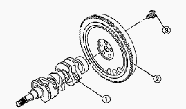
Lock the flywheel not to turn using the flywheel stopper. Remove the
flywheel screws, except for two which must be loosened and left as they
are. Set a flywheel puller , and remove the flywheel. Apply engine oil
to the flywheel screws.
Bearing case cover and crankshaft
Before disassembling, check the side clearance of crankshaft. Also check
it during reassembly. Remove the bearing case cover mounting screws.
Screw two removed screws into the screw hole of bearing case cover to
remove it. Stretch the washer and remove the bearing case screw. Pull
out the crankshaft. Install the crankshaft sub assembly, aligning the
screw hole of main bearing case with the screw hole of cylinder block.
Apply engine oil to the seat and thread of bearing case screw. After
tightening it, bend the washer firmly. Install the bearing case cover to
position the casting mark on it upward. Tighten the bearing case cover
mounting screws with even force on the diagonal line.
Main Bearing Case Assembly
Be sure to install the thrust bearing with its oil groove facing
outward. Remove the two bearing case screws, and remove the main bearing
case assembly, being careful with the thrust bearing and crankshaft
bearing 2. Remove the main bearing case assemblies as above. Clean the
oil passage in the main bearing case. Apply dean engine oil on the
crankshaft bearing 2 and thrust bearings. Install the main bearing case
assemblies in the original positions. They are not interchangeable.
Kubota B1550, B6100, B6200 Engine
Troubleshooting
When Kubota D850 engine is difficult to start
Fuel is thick and doesn't flow - Check the fuel oil tank and fuel oil
filter. Remove water, dirt and other impurities. As all fuel oil will be
filtered by the filter, if there should be water or other foreign
matters on the filter, replace the filter.
Air or water mixed in fuel system - If air is in the fuel filter or
injection lines, the fuel pump will not work properly. To attain proper
fuel injection pressure, check carefully for loosened fuel lines, cap
nut, etc. Loosen air vent screws atop fuel filter and fuel injection
pump to eliminate all the air in the fuel oil system.
Thick carbon deposits on orifice of injection nozzle - This is caused
when water or dirt is mixed in the fuel. Clean the nozzle injection
piece, being careful not to damage the orifice. Check to see if nozzle
is working properly or not. If not, install a new nozzle.
Valve clearance is incorrect - Adjust valve clearance.
Leaking valves - Grind valve.
Fuel injection timing is incorrect - Adjust injection timing.
Engine oil becomes thick in cold weather and engine cranks slow - Change
grade of oil according to the weather (temperature).
Low compression - Bad valve or excessive wear of rings, pistons and
liners cause insufficient compression. Replace with new parts.
Battery is discharged and the engine will not crank - Charge battery.
Use decompression device. In winter, always remove battery from tractor,
charge fully and keep indoors. Install in tractor at time of use.
When Kubota D850 engine lacks power
Air cleaner is dirty or Fuel filter is dirty - Clean the element every
100-200 hours of operation.
Carbon around orifice of nozzle piece - Clean orifice and needle valve,
being very carefully not to damage the nozzle orifice. Check nozzle. If
defective, replace with new parts.
Compression is insufficient. Leaking valves - Bad valve and excessive
wear of rings, pistons and liners cause insufficient compression.
Replace with new parts. Grind valves.
Fuel is insufficient - Check fuel system.
Overheating of moving parts - Check lube oil system. Check to see if
lube oil filter is working properly. Filter screens or elements
deposited impurities would cause poor lubrication. Clean screens. Check
to see if bearing clearance are within factory specs. Check engine
timing.
Valves out of adjustment - Adjust to proper valve clearance.
Fuel injection pressure is incorrect - Adjust to proper pressure.
When Kubota D850 engine suddenly stops
Leak of fuel - Check the fuel tank and refill if necessary. Also check
the fuel system for air or leaks.
Bad nozzle - If necessary, replace with a new nozzle.
Moving parts are overheated due to shortage of lube oil or improper
lubrication - Check amount of engine oil with dipstick. Check
lubricating oil system. Check to see if element inside the lubricating
oil filter has become old and clogged. If necessary, replace with new
element. Check to see if the engine bearing clearances is within factory
specs.
When Kubota D850 engine must be stopped
immediately
Speed suddenly decreases or increases - Check the adjustments and timing
of injection and the fuel system.
Unusual sound is heard suddenly - Check all moving parts carefully.
Color of exhaust suddenly turns dark - Check the fuel injection system,
especially the fuel injection nozzle.
Bearing parts are overheated - Check the lubricating system.
Oil light lights up during operation - Check lubricating system. Check
to see if the engine bearing clearances are within factory specs. Check
the function of the regulating valve inside the oil filter. Check
pressure switch. Check filter base gasket.
Starter does not function
Defective Alternator rectifier - Repair Alternator and replace defective
rectifier. Dirty or corroded terminal contacts - Wash terminal with hot
water and tighten well. Bad brushes, armature or field - Replace.
________________________________________________________________________________
________________________________________________________________________________________
 SPECIFICATIONS
 LOADERS
 ENGINES
 INSTRUCTIONS
 PROBLEMS
________________________________________________________________________________________
 B2320
B2320 B2630
B2630 B2920
B2920 B3300SU
 BX2360
________________________________________________________________________________________
 L245
L245 L260
L260 L275
L275 L285
L285 L305
L305________________________________________________________________________________________
________________________________________________________________________________________
 D662
D662 D722
D722 D750
D750 D782
D782 D850
D850________________________________________________________________________________________
 LA302
LA302 LA304
LA304 LA340
LA340 LA344
LA344 LA351
LA351________________________________________________________________________________________
 BX2660
 L2501
L2501 L3240
L3240 L3540
L3540 L3940
L3940________________________________________________________________________________________
 D902
D902 D905
D905 D950
D950 D1005
D1005 D1100
D1100________________________________________________________________________________________
________________________________________________________________________________________
 B1630
B1630 BF400
BF400 BF400G
 LA181
LA181 LA203
LA203________________________________________________________________________________________
 LA211
LA211 LA243
LA243 LA271
LA271 LA272
LA272 LA301
LA301________________________________________________________________________________________
 L175
L175 L185
L185 L210
L210 L225
L225 L235
L235________________________________________________________________________________________
 D1105
D1105 D1503
D1503 D1703
D1703 D1803
D1803 V1200
V1200________________________________________________________________________________________
 L4400
L4400 L4600
L4600 L5040
L5040 L5740
L5740 MX4700
________________________________________________________________________________________
 LA352
LA352 LA364
LA364 LA401
LA401 LA402
LA402 LA403
LA403________________________________________________________________________________________
 LA434
LA434 LA463
LA463 LA481
LA481 LA482
LA482 LA504
LA504________________________________________________________________________________________
 V1205
V1205 V1305
V1305 V1505
V1505 V2203
V2203 V2403
V2403________________________________________________________________________________________
 B2710
B2710 BX23S
BX23S B3350
B3350 BX1880
 L4701
L4701________________________________________________________________________________________
 LA513
LA513 LA514
LA514 LA524
LA524 LA525
LA525 LA534
LA534________________________________________________________________________________________
 LA555
LA555 LA680
LA680 LA681
LA681 LA682
LA682 LA703
LA703________________________________________________________________________________________
 Z482
Z482 Z602
Z602 Z750
Z750 Z1100
Z1100 Z1300
Z1300________________________________________________________________________________________
 M100GX
 M135GX
 M6040
M6040 M8540
M8540 M95X
M95X________________________________________________________________________________________
 LA714
LA714 LA723
LA723 LA724
LA724 LA764
LA764 LA765
LA765________________________________________________________________________________________
 LA805
LA805 LA844
LA844 LA852
LA852 LA853
LA853 LA854
LA854________________________________________________________________________________________
 M5-091
 BX2680
 MX5200
 BX2380
 L3901
L3901________________________________________________________________________________________
 LA1002
 LA1055
 LA1065
 LA1153
 LA1154
________________________________________________________________________________________
 LA1251
 LA1301S
 LA1353
 LA1403
 LA1601S
________________________________________________________________________________________
 LA1854
 LA1944
 LA1953
 LA2253
 LM2605