
________________________________________________________________________________
Kubota B21, BX2680, B2301, B7500 Engine - Checking and Adjusting
Kubota D1005 Three-cylinder diesel engine used in B21, BX2680, B2301,
B7500 tractors.
Kubota B21, BX2680, B2301, B7500 - Engine
Components
Cylinder Block
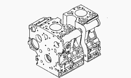
Kubota D1005 engine has a high durability tunnel-type cylinder block in
which the crank bearing component is a constructed body. Furthermore,
liner less type, allow effective cooling, less distortion, and greater
wear-resistance. The noise level is reduced to a minimum because each
cylinder has its own chamber.
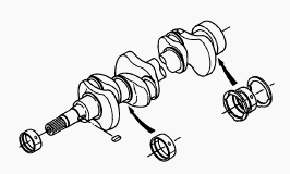
Crankshaft
The crankshaft with the connecting rod converts the reciprocating motion
of the piston into the rotating motion. The crankshaft is made of tough
special alloy steel, and the journals, pins and oil seal sliding
portions are induction hardened to increase the hardness for higher wear
resistance. The front journal is supported by a solid type bearing, the
intermediate journal by a split type, and the rear journal by a split
type with thrust bearings. The crankshaft is provided with an oil
gallery, through which engine oil is fed to the crankpin portion, and
lubricate it.
Rocker Arm
The rocker arm assembly includes the rocker arms, rocker arm brackets
and rocker arm shaft and converts the reciprocating movement of the push
rods to an open/close movement of the inlet and exhaust valves.
Lubricating oil is pressurized through the bracket to the rocker arm
shaft, which serves as a fulcrum so that the rocker arm and the entire
system are lubricated sufficiently.
Kubota B21, BX2680, B2301, B7500 - Flywheel
The flywheel is connected with the crankshaft, it stores the rotating
force in the combustion stroke as inertial energy to rotate the
crankshaft smoothly. The flywheel periphery is provided with marks
showing fuel injection timing and top dead center. The flywheel and
crankshaft can be fixed to each other at a certain point according to
the arrangement of flywheel mounting screw hole. On the circum ference
of the flywheel are stamped the top dead center (1TC) mark for the 1st
cylinder and four lines indicating every 0.087 rad. (5°) of crank angle
from 0.175 rad. (10°) to 0.436 rad. (25°) before mark 1TC.
Air Cleaner
The air cleaner is of a dry type with evacuator valve for easy
maintenance. The dust, while circulating in the air flow, is absorbed by
the element and thus prevented from entering the engine. The dust, while
circulating in the air flow, is absorbed by the element and thus
prevented from entering the engine.
Muffler
The muffler consists of an inner tube with a series of holes and outer
tube. The exhaust noises are absorbed and dumped, while the gas pass
through a series of holes on the inner tube.
Cylinder Head and Valves
Valve recessing - 0.4 mm. Clearance between Valve Stem and valve guide -
0.1 mm. Valve guide - 7.010 to 7.025 mm. Valve guide protrusion - 10 mm.
Valve seat width - 2.12 mm (0.0835 in.). Clearance between rocker arm
shaft and rocker arm - 0.10 mm. Rocker arm shaft - 11.973 to 11984 mm.
Push rod alignment - 0.25 mm.
Timing Gears and Camshaft
Crank gear/Idle gear - 0.032 to 0.115 mm. Idle gear/Cam gear - 0.036 to
0.114 mm. Idle gear/Injection pump gear 0.034 to 0.116 mm. Injection
pump gear/Governor gear 0.033 to 0.117 mm. Clearance between the idle
gear and the idle gear collar with a dial gauge - 0.9 mm. Clearance
between the cam gear and the camshaft stopper - 0.30 mm. Oil clearance
of camshaft - 0.050 to 0.091 mm. Camshaft bearing journal O.D. - 35.934
to 35.950 mm. Camshaft bearing I.D. - 36.000 to 36.025 mm. Clearance
between idle gear shaft and idle gear bushings - 0.020 to 0.054 mm. Idle
gear shaft O.D. - 25.959 to 25.975 mm.
Piston and Connecting Rod
Clearance between piston pin and small end bushing - 0.014 to 0.038 mm.
Small end bushing - 22.025 to 22.040 mm. Top ring - 0.25 to 0.40 mm.
Second ring - 1.25. Oil ring - 0.020 to 0.055 mm.
Crankshaft
Oil clearance between crankpin and crankpin bearing - 0.029 to 0.091 mm.
Oil clearance between crankshaft journal and cranks aft bearing 1 -
0.034 to 0.114 mm. Oil clearance between crankshaft journal and cranks
aft bearing 2 - 0.034 to 0.095 mm. Flywheel sway - 0.05 mm. Crankshaft
side clearance - 0.15 to 0.31 mm.
Cylinder
In general, maximum wear appears at direction of point which is about 20
mm (0.787 in.) from the top edge while minimum wear is at direction of
point. Wear of cylinder I.D. - 72.000 to 72.019 mm. Bore and finish the
cylinder inner wall using a hone to a diameter + 0.5 mm (0.0197 in.)
larger than the standard. The surface roughness after honing must be 1.2
to 2.0. Oversized cylinder - 72.500 to 72.519 mm.
Kubota B21, BX2680, B2301, B7500 - Lubrication
System
Oil Pump
The oil pump in Kubota D1005 engine is a trochoid pump. Inside the pump
body, the 10 lobe inner rotor is eccentrically engaged with the 11 lobe
outer rotor. The inner rotor is driven by the crankshaft, which in turn
rotate the outer rotor. When the inner rotor rotates, the outer rotor
also rotates in the same direction. The two rotors have differences in
lobe number and center, which generates space between lobes. At
position, there is little space between lobes in the inlet port. As the
rotor rotates towards position, the space between the lobes becomes
larger, creating a negative pressure which sucks in oil. Outside the
inlet port, the space between the lobes becomes gradually smaller, and
oil pressure increases. At position, oil is discharged from the outlet
port.
Rotor Lobe Clearance
Measure the clearance between lobes of the inner rotor and the outer
rotor with a feeler gauge. If the clearance exceeds the factory
specification, replace the oil pump rotor assembly. Outer and inner
rotor clearance - 0.06 to 0.18 mm.
Clearance between Outer Rotor and Pump Body
Measure the clearance between the outer rotor and the pump body with a
feeler gauge. If the clearance exceeds the factory specification,
replace the oil pump rotor assembly. Radial clearance between outer
rotor and pump body - 0.10 to 0.18 mm.
Clearance between Rotor and Cover
Put a strip of press gauge onto the rotor face with grease. Install the
cover and tighten the screws. Remove the cover carefully, and measure
the width of the press gauge with a sheet of gauge. If the clearance
exceeds the factory specification, replace oil pump rotor assembly. End
clearance between rotor and cover - 0.025 to 0.75 mm.
Relief Valve
The relief valve prevents the damage of the lubricating system due to
high oil pressure. This relief valve is a ball type direct acting relief
valve, and is best suited for low pressures. When oil pressure exceeds
the upper limit, the ball is pushed back by the pressure oil and the oil
escapes.
Kubota B21, BX2680, B2301, B7500 - Cooling
System
The cooling system consists of a radiator, centrifugal water pump,
suction fan and thermostat. The water is cooled through the radiator
core, and the fan set behind the radiator pulls cooling air through the
core to improve cooling. The water pump sucks the cooled water, forces
it into the cylinder block and draws out the hot water. Then the cooling
is repeated. Furthermore, to control temperature of water, a thermostat
is provided in the system. When the thermostat opens, the water moves
directly to radiator, but when it closes, the water moves toward the
water pump through the bypass between thermostat and water pump. The
opening temperature of thermostat is approx. 82C (180F).
Radiator
The radiator core consists of water carrying tubes and fins at a right
angle to the tubes. Heat of hot water in the tubes is radiated from the
tube walls and fins. KUBOTA's engine uses corrugated fin type core which
has a ligl1t weight and high heat transfer rate. Clogging is minimized
by the louver less corrugated fins.
Radiator Cap
The radiator cap is for sustaining the internal pressure of the cooling
system at the specified level 88 kPa (0.9 kgf/cm2, 13 psi) when the
engine is in operation. The cap consists of a pressure valve a vacuum
valve, valve springs, gasket, etc. Cooling water is pressurized by
thermal expansion of steam, and as its boiling temperature rises,
generation of air bubbles will be suppressed. (Air bubbles in cooling
water lowers the cooling effect).
Fan Belt Tension
Press the fan belt between fan drive pulley and dynamo pulley (or
alternator pulley) at 98N (10 kgf, 221bs) of force. If the deflection is
not within the factory specifications, loosen the bolts, and relocate
the dynamo (or alternator) to adjust. If the belt is damaged or worn,
replace the belt.
Thermostat's Valve Opening Temperature
Push down the thermostat valve and insert a string between the valve and
the valve seat. Place the thermostat and a thermometer in a container
with water and gradually heat the water. Hold the string to suspend the
thermostat in the water. When the water temperature rises, the
thermostat valve will open, allowing it to fall down from the string.
Read the temperature at this moment on the thermometer. Continue heating
the water and read the temperature when the valve has risen by about 6mm
(0.236 in.). If the measurement is not acceptable, replace the
thermostat.
Radiator Water Leakage
Pour a specified amount of water into the radiator. Set a radiator
tester. Increase water pressure to the specified pressure. Check each
section for water leakage. When water leakage is excessive, replace the
radiator. If water leakage is caused by a small pinhole, correct the
radiator with radiator cement.
Radiator Cap Air Leakage
Set a radiator tester to the radiator cap. Apply the specified pressure
of 98.1 kPa (0.9 kgf/cm2, 12.8 psi). Check if the pressure drop to less
than 59 kPa (0.6 kgf/cm2, 9 psi) in 10 seconds. If the pressure is less
than the factory specification, replace it.
Kubota B21, BX2680, B2301, B7500 - Fuel System
Injection Pump
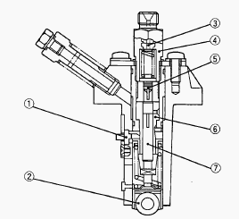
A Bosch MD type mini pump is used for the injection pump. It is small,
lightweight and easy to handle. The plunger with a left-hand lead
reciprocates via the tappet roller by means of the camshaft fuel cam,
causing the fuel to be delivered into the injection nozzle. No fuel
delivery - At the engine stop position of the control rack, the
lengthwise slot on the plunger aligns with the feed hole. And the
delivery chamber is led to the feed hole during the entire stroke of the
plunger. The pressure in the delivery chamber does not build up and no
fuel can be forced to the injection nozzle. Fuel delivery - The plunger
is rotated by the control rack. When the plunger is pushed up, the hole
is closed. The pressure in the delivery chamber builds up and
force-feeds the fuel to the injection nozzle until the control groove
meets the feed hole. The amount of the fuel corresponds to the distance.
The pump element is consist of the plunger and cylinder. The sliding
surfaces are super-precision machined to maintain injection pressure at
engine low speeds. Since the driving face fits in the control sleeve,
the plunger is rotated by the movement of the control rack to increase
or decrease of fuel delivery. As described above, the plunger is
machined to have the slot and the control groove.
The delivery valve consists of the delivery valve and delivery valve
seat. The delivery valve performs the following functions. Reverse flow
preventing function - If the fuel flow reverse from the injection nozzle
side when the plunger lowers, the time lag between the next delivery
start and the nozzle injection start increases. To avoid this, the
delivery chamber to injection pipe interruption by delivery valve
prevents this reverse flow, thus keeping fuel always filled in the
nozzle and pipe. Suck-back function - After completing the fuel
delivery, the delivery valve lowers, and the relief plunger end contacts
the delivery valve seat. The valve further lowers until its seat surface
seats firmly the delivery valve seat. During this time, the amount of
fuel corresponding to is sucked back from inside the injection pipe, the
pressure inside the pipe is reduced, thus leading to an improved
injection shut off and preventing after leakage dribbling.
Dumping Valve: At fuel injection - Since dumping valve is pushed up to
press the spring, fuel is pressure-fed to injection nozzle the same as
without dumping valve. At suck-back - At suck-back by delivery valve
after fuel injection fuel returns through dumping valve orifice.
Generally second injection is apt to occur by reflex pressure due to
reaction of sudden pressure drop when changing into suck-back by
delivery valve from high injection pressure. As a result of preventing
this second injection perfectly by dumping valve and dissolving nozzle
clogging, durability of injection nozzle is improved.
Injection Nozzle
This nozzle is of flat-cut-provided double throttle type. This type of
nozzle is designed to control the injection quantity when the lift rate
is low at start of the injection quantity when the lift rate is low at
start of the injection, and to cut down on the knocking sound caused by
excessive fuel injection by giving the needle valve section more taper
than before to prevent the rapid increase in the injection quantity when
the initial injection turns into the full force injection. Also,
employed to prevent the injection quantity loss in the throttle section
caused by carbon, the flat cut provided at the needle valve section
helps the throttle with stand long use and reduce as much knocking sound
as when it was new. The heat seal is employed to improve the durability
and reliability of the nozzle. The injection pressure is 13.73 to 14.71
MPa (140 to 150 kgf/cm2, 1991 to 2133 psi), and is adjusted with
adjusting washers.
Kubota B21, BX2680, B2301, B7500 - Injection
Timing
When inspecting the fuel injection timing, the timing control actuates
during starting and the correct fuel injection timing cannot be
measured. Remove the injection pipes. Remove the engine stop solenoid,
push in the control rack of the injection pump by 5 mm (0.2 in.) and
hold it at that position. Turn the flywheel counterclockwise until fuel
flows from the delivery valve holder. Continue to turn the flywheel
slowly, and stop it as soon as the fuel level at the tip of the delivery
valve holder begins to increase. Check to see if the timing angle lines
on the flywheel is aligned with the alignment mark. If the timing is out
of adjustment, readjust the timing with shims.
Fuel Tightness of Pump Element
Remove the injection pipes and glow plugs, and install the pressure
tester. With the speed control lever at the full injection position,
turn the crankshaft counterclockwise (facing the flywheel). If the
pressure does not build up to the fuel injection pressure, replace the
delivery valve with new one and test again. If the pressure does not
built up more than the fuel injection pressure, replace the injection
pump assembly. After replacing only pump element, the amount of
injection should be adjusted on a specified test bench.
Fuel Tightness of Delivery Valve
The delivery valve is checked in the same way as the pump element. Turn
the flywheel counterclockwise to make the pressure gauge indicate 14.7
MPa (150 kgf/cm2, 2133 psi). Set the mark on the flywheel of the
cylinder being checked to the position at 90° clockwise from the punch
mark on the rear end plate (This lowers the pressure inside the delivery
chamber). If it takes the pressure five seconds or more to drop from
14.7 MPa (150 kgf/cm2, 2133 psi) to 13.7 MPa (140 kgf/cm2, 1991 psi) the
delivery valve can be used. If the measured value stays below the
allowable limit, replace the pump assembly or the delivery valve.
Nozzle Injection Pressure
Set the injection nozzle to the nozzle tester. Slowly move the tester
handle to measure the pressure at which fuel begins jetting out from the
nozzle. If the measurement is not within the factory specifications,
disassemble the injection nozzle, and change adjusting washer until the
proper injection pressure is obtained. Pressure variation with 0.025 mm
(0.00098 in.) difference of adjusting washer thickness. Approx. 588 kPa
(6 kgf/cm 2, 85 psi).
Nozzle Spraying Condition
Set the injection nozzle to a nozzle tester and check the nozzle
spraying condition. If the spraying condition is defective, replace the
nozzle piece.
Fuel Tightness of Needle Valve Seat
Set the injection nozzle to a nozzle tester. Apply a pressure 12.75 MPa
(130kgf/cm2, 1849 psi). After keeping the nozzle under this pressure for
10 seconds, check to see if fuel leaks from the nozzle. If fuel should
leak, replace the nozzle piece.
Kubota B21, BX2680, B2301, B7500 - Engine
Separating
Draining Cooling Water
Loosen the drain cock from the radiator hose to drain cooling water.
Remove the radiator cap to drain cooling water completely.
Draining Engine Oil
Start and warm up Kubota D1005 engine for approx. 5 minutes. Place an
oil pan underneath the engine. Remove the drain plug to drain oil. Screw
in the drain plug. Fill the engine oil up to the upper line on the
dipstick.
Drain the Transmission Oil
Place oil pans underneath the transmission case. Remove the four drain
plugs at the bottom of the transmission case. Drain the transmission
oil. After draining, screw in the four drain plugs. Fill new oil from
filling port after removing the filling plug up to the upper notch on
the dipstick. After running the engine for few minutes, stop it and
check the oil level again, if low, add oil prescribed level.
Transmission oil capacity: Manual transmission - 11 L, HST transmission
- 12 L.
Hood and Side Cover
Open the hood from front and remove the spling lock pin and remove the
food with hood rod for keeping it open. Remove the front grille. Remove
the right and left side cover. Disconnect the battery cords.
Radiator Hoses, Muffler Pipe and Hydraulic
Pipes
Loosen the clamps and disconnect radiator hoses. Remove the muffler
pipe. Disconnect the radiator stay and then dismount the radiator.
Dismount the battery. Loosen the clamps of hydraulic hoses and remove
the battery stay with oil cooler then remove the delivery pipe (from
HST) and return pipe (from oil cooler) (HST type).
Fuel Hoses and Fuel Filter
Close the fuel filter cock. Disconnect the fuel hose between fuel pump
and fuel filter at the fuel filter side. Remove the fuel filter mounting
screw and remove the fuel filter from the bracket.
Propeller Shaft Cover and Coupling
Loosen the clamp and slide the propeller shaft cover to the rear. Tap
out the spring pin and then slide the coupling to the rear.
Drag Link
Steer the front wheels to the left. Remove the slotted nut and
disconnect the drag link from the knuckle arm.
Steering Wheel
Remove the steering wheel cap. Remove the steering wheel mounting nut
and remove the steering wheel with a steering wheel puller.
Meter Pedal and Panel Under Cover
Remove the meter panel and disconnect the meter panel connector and
hour-meter cable from the meter panel. Then remove the meter panel. Tap
out the spring pin and remove the hand accelerator lever. Disconnect the
combination switch connector and main switch connector. Remove the panel
under cover mounting screw, and take off the panel under cover.
Kubota B21, BX2680, B2301, B7500 - Fuel Tank
Remove the fuel tank frame stay. Disconnect the regulator and hazard
unit connectors and remove the lead wire for fuel gauge. Remove the fuse
box. Disconnect the overflow hoses of fuel line. Remove the tank flame
with fuel tank.
Universal Joint and Bearing Holder
Loosen the clamp and slide the universal joint cover to the rear. Tap
out the spring pins and then slide the universal joint to the rear.
Remove the bearing holder and universal joint. Make sure the yokes of
universal joints must always be in the same plane as shown in the
figure. Apply grease to the splines of the propeller shaft and universal
joint. When inserting the spring pins, face their splits in the
direction parallel to the universal joint.
Suction Pipe, Delivery Pipe and Power Steering
Pipes and Others
Remove the foot accelerator rod. Remove the power steering delivery
pipe. Remove the power steering return pipe (HST Type). Loosen the joint
bolt of delivery pipe on the hydraulic cylinder and disconnect the flare
nut of 3-point hitch delivery pipe. Remove the fuel filter bracket.
Loosen the cramp of suction hose and remove the suction hose from the
hydraulic pump. Remove the shutter plate.
Separating the Engine from Clutch Housing
Remove the wiring harness. Place the jack under the center frame. Hoist
the engine by the chain at the engine hook. Remove the engine mounting
screws and separate the engine from the clutch housing.
________________________________________________________________________________
________________________________________________________________________________________
 SPECIFICATIONS
 LOADERS
 ENGINES
 INSTRUCTIONS
 PROBLEMS
________________________________________________________________________________________
 B2320
B2320 B2630
B2630 B2920
B2920 B3300SU
 BX2360
________________________________________________________________________________________
 L245
L245 L260
L260 L275
L275 L285
L285 L305
L305________________________________________________________________________________________
________________________________________________________________________________________
 D662
D662 D722
D722 D750
D750 D782
D782 D850
D850________________________________________________________________________________________
 LA302
LA302 LA304
LA304 LA340
LA340 LA344
LA344 LA351
LA351________________________________________________________________________________________
 BX2660
 L2501
L2501 L3240
L3240 L3540
L3540 L3940
L3940________________________________________________________________________________________
 D902
D902 D905
D905 D950
D950 D1005
D1005 D1100
D1100________________________________________________________________________________________
________________________________________________________________________________________
 B1630
B1630 BF400
BF400 BF400G
 LA181
LA181 LA203
LA203________________________________________________________________________________________
 LA211
LA211 LA243
LA243 LA271
LA271 LA272
LA272 LA301
LA301________________________________________________________________________________________
 L175
L175 L185
L185 L210
L210 L225
L225 L235
L235________________________________________________________________________________________
 D1105
D1105 D1503
D1503 D1703
D1703 D1803
D1803 V1200
V1200________________________________________________________________________________________
 L4400
L4400 L4600
L4600 L5040
L5040 L5740
L5740 MX4700
________________________________________________________________________________________
 LA352
LA352 LA364
LA364 LA401
LA401 LA402
LA402 LA403
LA403________________________________________________________________________________________
 LA434
LA434 LA463
LA463 LA481
LA481 LA482
LA482 LA504
LA504________________________________________________________________________________________
 V1205
V1205 V1305
V1305 V1505
V1505 V2203
V2203 V2403
V2403________________________________________________________________________________________
 B2710
B2710 BX23S
BX23S B3350
B3350 BX1880
 L4701
L4701________________________________________________________________________________________
 LA513
LA513 LA514
LA514 LA524
LA524 LA525
LA525 LA534
LA534________________________________________________________________________________________
 LA555
LA555 LA680
LA680 LA681
LA681 LA682
LA682 LA703
LA703________________________________________________________________________________________
 Z482
Z482 Z602
Z602 Z750
Z750 Z1100
Z1100 Z1300
Z1300________________________________________________________________________________________
 M100GX
 M135GX
 M6040
M6040 M8540
M8540 M95X
M95X________________________________________________________________________________________
 LA714
LA714 LA723
LA723 LA724
LA724 LA764
LA764 LA765
LA765________________________________________________________________________________________
 LA805
LA805 LA844
LA844 LA852
LA852 LA853
LA853 LA854
LA854________________________________________________________________________________________
 M5-091
 BX2680
 MX5200
 BX2380
 L3901
L3901________________________________________________________________________________________
 LA1002
 LA1055
 LA1065
 LA1153
 LA1154
________________________________________________________________________________________
 LA1251
 LA1301S
 LA1353
 LA1403
 LA1601S
________________________________________________________________________________________
 LA1854
 LA1944
 LA1953
 LA2253
 LM2605