
________________________________________________________________________________
Kubota B2530, B2400, B2410 Engine - Checking and Service
Kubota B2530, B2400, B2410 tractors are equipped with a D1105 3-cylinder
diesel engine.
Kubota B2530, B2400, B2410 Engine Checking
Checking Fan Belt Tension
Be sure to stop engine before checking belt tension. Stop the engine and
remove the key. Apply moderate thumb pressure to belt between pulleys.
If tension is incorrect, loosen the alternator mounting bolts and, using
a lever placed between the alternator and the engine block, pull the
alternator out until the deflection of the belt falls within acceptable
limits. Replace fan belt if it is damaged. Fan belt tension - Deflection
of between 7 to 9 mm (0.28 to 0.34 in.) when the belt is pressed in the
middle of the span.
Checking Fuel Line
Check to see that all line and hose clamps are tight and not damaged. If
hoses and clamps are found worn or damaged, replace or repair them at
once. The fuel line is made of rubber and ages regardless of period of
service. Replace the fuel pipe together with the clamp every two years
and securely tighten. However if the fuel pipe and clamp are found
damaged or deteriorated earlier than two years, then change or remedy.
After the fuel line and clamp have been changed, bleed the fuel system.
Changing Engine Oil
Start and warm up the engine for approx. 5 minutes. Place an oil pan
underneath the engine. To drain the used oil, remove the drain plug at
the bottom of the engine and drain the oil completely. Screw in the
drain plug. Fill new oil up to upper line on the dipstick. When using an
oil of different manufacture or viscosity from the previous one, remove
all of the old oil. Never mix two different types of oil.
Replacing Engine Oil Filter Cartridge
Remove the oil filter cartridge with the filter wrench. Apply a slight
coat of oil onto the cartridge gasket. To install the new cartridge,
screw it in by hand. Over tightening may cause deformation of rubber
gasket. After the new cartridge has been replaced, the engine oil
normally decrease a little. Thus see that the engine oil does not leak
through the seal and be sure to read the oil level on the dipstick.
Then, replenish the engine oil up to the specified level.
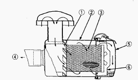
Cleaning Air Cleaner Element
Remove the air cleaner cover and primary element. Clean the primary
element if: When dry dust adheres to the element, blow compressed air
from the inside turning the element. Pressure of compressed air must be
under 686 kPa (7 kgf/cm2, 99 psi). When carbon or oil adheres to the
element, soak the element in detergent for 15 minutes then wash it
several times in water, rinse with clean water and dry it naturally.
After element is fully dried, inspect inside of the element with a light
and check if it is damaged or not. When replacing the air cleaner
primary element, replace the secondary element as well: Once a year or
after every six times of cleaning, whichever comes first.
Cleaning Fuel Filter
This job should not be done in the field, but in a clean place. Loosen
and remove the fuel filter bowl, and rinse the inside with kerosene.
Take out the filter element and dip it in the kerosene to rinse. After
cleaning, reassemble the fuel filter, keeping out dust and dirt. Bleed
the fuel system. When the fuel filter bowl has been removed, fuel stops
flowing from the fuel tank. If the fuel tank is almost full, however,
the fuel will flow back from the fuel return pipe to the fuel filter.
Before the above checking, make sure the fuel tank is less than
half-full.
Checking Radiator Hose and Hose Clamp
Check to see if radiator hoses are properly fixed every 200 hours of
operation or six months, whichever comes first. If hose clamps are loose
or water leaks, tighten bands securely. Replace hoses and tighten hose
clamps securely, if radiator hoses are swollen, hardened or cracked.
Replace hoses and hose clamps every 2 years or earlier if checked and
found that hoses are swollen, hardened or cracked.
Checking Intake Air Line
Check to see that hoses and hose clamps are tight and not damaged. If
hoses and clamps are found worn or damaged, replace or repair them at
once.
Flush Cooling System and Changing Coolant
Stop the engine and let cool down. To drain the coolant, open the
radiator drain cock, and remove radiator cap. The radiator cap must be
removed to completely drain the coolant. After all coolant is drained,
close the drain plug. Fill with clean water and cooling system cleaner.
Follow directions of the cleaner instruction. After flushing, fill with
clean water and anti-freeze until the coolant level is just below the
port. Start and operate the engine for few minutes. Stop the engine.
Check coolant level and add coolant if necessary. Install the radiator
cap securely.
Bleeding Fuel System
Air must removed: When the fuel filter or lines are removed. When tank
is completely empty. After the tractor has not been used for a long
period of time. Bleeding procedure is as follows: Fill the fuel tank
with fuel. Start the engine and run for about 30 seconds, and then stop
the engine.
Kubota B2530, B2400, B2410 - Engine Servicing
Cylinder Head Surface Flatness
Clean the cylinder head surface. Place a straightedge on the cylinder
head's four sides and two diagonal. Measure the clearance with a feeler
gauge. If the measurement exceeds the allowable limit, correct it with a
surface grinder. Do not place the straightedge on the combustion
chamber. Be sure to check the valve recessing after correcting. Cylinder
head surface flatness - Allowable limit 0.05 mm (0.0019 in).
Cylinder Head Flaw
Prepare an air spray red check. Clean the surface of the cylinder head
with detergent. Spray the cylinder head surface with the red permeative
liquid. Leave it five to ten minutes after spraying. Wash away the red
permeative liquid on the cylinder head surface with the detergent. Spray
the cylinder head surface with white developer. If flawed, it can be
identified as red marks.
Valve Recessing
Clean the cylinder head surface, valve face and valve seat. Insert the
valve into the valve guide. Measure the valve recessing with a depth
gauge. If the measurement exceeds the allowable limit, replace the
valve. If it still exceeds the allowable limit after replacing the
valve, correct the valve seat face of the cylinder head with a valve
seat cutter or valve seat grinder. Then, correct the cylinder head
surface with a surface grinder, or replace the cylinder head. Valve
recessing - 0.05 (protrusion) to 0.15 (recessing) mm.
Clearance between Valve Stem and Valve Guide
Remove carbon from the valve guide section. Measure the valve stem O.D.
with an outside micrometer. Measure the valve guide I.D. with a small
hole gauge, and calculate the clearance. If the clearance exceeds the
allowable limit, replace the valves. If it still exceeds the allowable
limit, replace the valve guide. Clearance between valve stem and valve
guide - 0.035 to 0.065 mm (0.00138 to 0.00256 in). Valve stem O.D. -
6.960 to 6.975 mm (0.27402 to 0.27461 in). Valve guide I.D. - 7.010 to
7.025 mm (0.27599 to 0.27657 in).
Replacing Valve Guide
Press out the used valve guide using a valve guide replacing tool. Clean
a new valve guide and valve guide bore, and apply engine oil to them.
Press in a new valve guide using a valve guide replacing tool. Ream
precisely the I.D. of the valve guide to the specified dimension. Valve
guide I.D. (Intake and exhaust) - 7.010 to 7.025 mm (0.27599 to 0.27657
in).
Valve Seating
Coat the valve face lightly with prussian blue and put the valve on its
seat to check the contact. If the valve does not seat all the way around
the valve seat or the valve contact is less than 70%, correct the valve
seating as follows. If the valve contact does not comply with the
reference value, replace the valve or correct the contact of valve
seating.
Correcting Valve and Valve Seat
After correcting the valve seat, be sure to check the valve recessing.
Correct the valve with a valve refacer. Slightly correct the seat
surface with a 1.047 rad. (60°) (intake valve) or 0.785 rad. (45°)
(exhaust valve) seat cutter. Resurface the seat surface with a 0.523
rad. (30°) valve seat cutter to intake valve seat and with a 0.262 rad.
(15°) valve seat cutter to exhaust valve seat so that the width is close
to specified valve seat width (2.12 mm, 0.0835 in.). After resurfacing
the seat, inspect for even valve seating, apply a thin film of compound
between the valve face and valve seat, and fit them with valve lapping
tool. Check the valve seating with prussian blue. The valve seating
surface should show good contact all the way around.
Valve Lapping
Apply compound evenly to the valve lapping surface. Insert the valve
into the valve guide. Lap the valve onto its seat with a valve flapper
or screwdriver. After lapping the valve, wash the compound away and
apply oil, then repeat valve lapping with oil. Apply prussian blue to
the contact surface to check the seated rate. If it is less than 70 0/0,
repeat valve lapping again. When valve lapping is performed, be sure to
check the valve recessing and adjust the valve clearance after
assembling the valve.
Free Length and Tilt of Valve Spring
Measure the free length (A) of valve spring with vernier calipers. If
the measurement is less than the allowable limit, replace it. Put the
valve spring on a surface plate, place a square on the side of the valve
spring. Check to see if the entire side is in contact with the square.
Rotate the valve spring and measure the maximum tilt. If the measurement
exceeds the allowable limit, replace it. Check the entire surface of the
valve spring for scratches. If there is any defect, replace it. Free
length - Allowable limit 36.5 mm . Tilt 1.0 mm (0.039 in).
Valve Spring Setting Load
Place the valve spring on a tester and compress it to the same length it
is actually compressed in the engine. Read the compression load on the
gauge. If the measurement is less than the allowable limit, replace it.
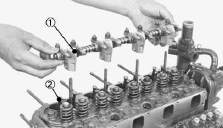
Oil Clearance between Rocker Arm and Rocker
Arm Shaft
Measure the rocker arm shaft 0.0. with an outside micrometer. Measure
the rocker arm 1.0. with an inside micrometer, and then calculate the
oil clearance. If the oil clearance exceeds the allowable limit, replace
the rocker arm and measure the oil clearance again. If it still exceeds
the allowable limit, replace also the rocker arm shaft. Oil clearance
between rocker arm and rocker arm shaft - 0.016 to 0.045 mm (0.00063 to
0.00177 in). Rocker arm shaft O.D. - 11.973 to 11.984 mm (0.47138 to
0.47181 in). Rocker arm I.D. - 12.000 to 12.018 mm (0.47244 to 0.47315
in).
Push Rod Alignment
Place the push rod on V blocks. Measure the push rod alignment. If the
measurement exceeds the allowable limit, replace the push rod. Push rod
alignment Allowable limit - 0.25 mm (0.0098 in).
Oil Clearance between Tappet and Tappet Guide
Bore
Measure the tappet O.D. with an outside micrometer. Measure the I.D. of
the tappet guide bore with a cylinder gauge, and calculate the oil
clearance. If the oil clearance exceeds the allowable limit or the
tappet is damaged, replace the tappet. Oil Clearance between tappet and
tappet guide bore 0.020 to 0.062 mm (0.00079 to 0.00244 in). Allowable
limit 0.07 mm (0.0028 in). Tappet O.D. - 19.959 to 19.980 mm (0.78579 to
0.78661 in). Tappet guide bore I.D. - 20.000 to 20.021 mm (0.78740 to
0.78823 in).
Kubota B2530, B2400, B2410 - Timing Gears,
Camshaft and Fuel Camshaft
Timing Gear Backlash
Set a dial indicator (lever type) with its tip on the gear tooth. Move
the gear to measure the backlash, holding its mating gear. If the
backlash exceeds the allowable limit, check the oil clearance of the
shafts and the gear. If the oil clearance is proper, replace the gear.
Backlash between idle gear and crank gear 0.032 to 0.115 mm / 0.00120 to
0.00453 in. Backlash between idle gear and cam gear 0.036 to 0.114 mm /
0.00142 to 0.00449 in. Backlash between idle gear and injection pump
gear 0.034 to 0.116 mm / 0.00134 to 0.00457 in. Backlash between
injection pump gear and governor gear 0.030 to 0.117 mm / 0.00118 to
0.00461 in.
Idle Gear Side Clearance
Set a dial indicator with its tip on the idle gear. Measure the side
clearance by moving the idle gear to the front and rear. If the
measurement exceeds the allowable limit, replace the idle gear collar.
Idle gear side clearance - 0.050 to 0.150 mm (0.0020 to 0.0059 in).
Camshaft Side Clearance
Set a dial indicator with its tip on the camshaft. Measure the side
clearance by moving the cam gear to the front and rear. If the
measurement exceeds the allowable limit, replace the camshaft stopper.
Camshaft side clearance - 0.07 to 0.22 mm (0.0028 to 0.0087 in).
Camshaft Alignment
Support the camshaft with V blocks on the surface plate at both end
journals. Set a dial indicator with its tip on the intermediate journal.
Measure the camshaft alignment. If the measurement exceeds the allowable
limit, replace the camshaft. Camshaft alignment - Allowable limit 0.01
mm / 0.0004 in.
Cam Height
Measure the height of the cam at its highest point with an outside
micrometer. If the measurement is less than the allowable limit, replace
the camshaft. Cam height of intake - 28.80 mm / 1.1339 in. Cam height of
exhaust - 29.00 mm / 1.1417 in.
Oil Clearance of Camshaft Journal
Measure the camshaft journal O.D. with an outside micrometer. Measure
the cylinder block bore I.D. for camshaft with a cylinder gauge, and
calculate the oil clearance. If the oil clearance exceeds the allowable
limit, replace the camshaft. Oil clearance of camshaft journal 0.00197
to 0.00358 in. Camshaft journal O.D. Factory spec. 35.934 to 35.950 mm /
1.41473 to 1.41535 in. Cylinder block bore I.D. - 36.000 to 36.025 mm /
1.41732 to 1.41830 in.
Oil Clearance between Idle Gear Shaft and Idle
Gear Bushing
Measure the idle gear shaft O.D. with an outside micrometer. Measure the
idle gear bushing I.D. with an inside micrometer, and calculate the oil
clearance. If the oil clearance exceeds the allowable limit, replace the
bushing. If it still exceeds the allowable limit, replace the idle gear
shaft. Oil clearance between idle gear shaft and Idle Gear Bushing 0.020
to 0.054 mm / 0.00079 to 0.00213 in. Idle gear shaft O.D. 25.967 to
25.980 mm / 1.02232 to 1.02283 in. Idle gear bushing I.D. 26.000 to
26.021 mm / 1.02362 to 1.02445 in.
Replacing Idle Gear Bushing
Press out the used idle gear bushing using an idle gear bushing
replacing tool. Clean a new idle gear bushing and idle gear bore, and
apply engine oil to them. Press in a new bushing using an idle gear
bushing replacing tool, until it is flush with the end of the idle gear.
Kubota B2530, B2400, B2410 - Piston and
Connecting Rod
Piston Pin Bore O.D.
Measure the piston pin bore O.D. in both the horizontal and vertical
directions with a cylinder gauge. If the measurement exceeds the
allowable limit, replace the piston. Piston pin bore O.D. 22.000 to
22.013 mm / 0.86614 to 0.86665 in.
Oil Clearance between Piston Pin and Small End
Bushing
Measure the piston pin O.D. where it contacts the bushing with an
outside micrometer. Measure the small end bushing I.D. with an inside
micrometer, and calculate the oil clearance. If the oil clearance
exceeds the allowable limit, replace the bushing. If it still exceeds
the allowable limit, replace the piston pin. Oil clearance between
piston pin and small end bushing 0.014 to 0.038 mm / 0.00055 to 0.00150
in. Piston pin O.D. 22.002 to 22.011 mm / 0.86622 to 0.86657 in. Small
end bushing I.D. 22.025 to 22.040 mm / 0.86713 to 0.86771 in.
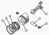
Replacing Small End Bushing
Press out the used bushing using a small end bushing replacing tool.
Clean a new small end bushing and bore, and apply engine oil to them.
Insert a new bushing onto the tool and press-fit it with a press so that
the seam (1) of bushing positions as shown in the figure, until it is
flash with the connecting rod. Drill a hole to the bushing with aligning
the oil hole (2) of connecting rod using 4.0 mm dia. (0.157 in. dia.)
drill.
Piston Ring Gap
Insert the piston ring into the lower part of the cylinder (the least
worn out part) with a piston ring compressor and piston. Measure the
ring gap with a feeler gauge. If the measurement exceeds the allowable
limit, replace the piston ring. Top ring and Second ring - 0.25 to 0040
mm / 0.0098 to 0.0157 in. Oil ring - 0.25 to 0045 mm / 0.0098 to 0.0177
in.
Clearance between Piston Ring and Piston Ring
Groove
Clean the rings and the ring grooves, and install each ring in its
groove. Measure the clearance between the ring and the groove with a
feeler gauge. If the clearance exceeds the allowable limit, replace the
piston ring. If the clearance still exceeds the allowable limit with new
ring, replace the piston. Second ring - 0.085 to 0.112 mm / 0.00335 to
0.00441 in. Oil ring - 0.020 to 0.055 mm / 0.00079 to 0.00217 in.
Connecting Rod Alignment
Remove the crankpin bearing, and install the connecting rod cap. Install
the piston pin in the connecting rod. Install the connecting rod on the
connecting rod alignment tool. Put a gauge over the piston pin, and move
it against the face plate. If the gauge does not fit squarely against
the face plate, measure the space between the pin of the gauge and the
face plate. If the measurement exceeds the allowable limit, replace the
connecting rod.
Kubota B2530, B2400, B2410 - Crankshaft
Crankshaft Side Clearance
Set a dial indicator with its tip on the end of the crankshaft. Measure
the side clearance by moving the crankshaft to the front and rear. If
the measurement exceeds the allowable limit, replace the thrust
bearings. If the same size bearing is useless because of the crankshaft
journal wear, replace it with an oversize. Crankshaft side clearance
0.15 to 0.31 mm / 0.0059 to 0.0122 in.
Crankshaft Alignment
Support the crankshaft with V blocks on the surface plate at both end
journals. Set a dial indicator with its tip on the intermediate journal.
Measure the crankshaft alignment. If the measurement exceeds the
allowable limit, replace the crankshaft.
Oil Clearance between Crankpin and Crankpin Bearing
Clean the crankpin and crankpin bearing. Put a strip of plastigage on
the center of the crankpin. Install the connecting rod cap and tighten
the connecting rod screws to the specified torque, and remove the cap
again. Measure the amount of the flattening with the scale, and get the
oil clearance. If the oil clearance exceeds the allowable limit, replace
the crankpin bearing. If the same size bearing is useless because of the
crankpin wear, replace it with an undersize one. Never insert the
plastigage into the crankpin oil hole. Be sure not to move the
crankshaft while the connecting rod screws are tightened. Oil clearance
between crankpin and crankpin bearing 0.029 to 0.091 mm / 0.00114 to
0.00358 in. Crankpin O.D. 39.959 to 39.975 mm / 1.57319 to 1.57382 in.
Crankpin bearing I.D. 40.004 to 40.050 mm / 1.57496 to 1.57677 in.
Oil Clearance between Crankshaft Journal and Crankshaft Bearing 1
Measure the O.D. of the crankshaft front journal with an outside
micrometer. Measure the I.D. of the crankshaft bearing 1 with an inside
micrometer, and calculate the oil clearance. If the oil clearance
exceeds the allowable limit, replace the crankshaft bearing 1. If the
same size bearing is useless because of the crankshaft journal wear,
replace it with an undersize one. Oil clearance between crankshaft
journal and crankshaft bearing 1 - 0.034 to 0.114 mm / 0.00134 to
0.00449 in. Crankshaft journal O.D. - 47.934 to 47.950 mm / 1.88716 to
1.88779 in. Crankshaft bearing 1 I.D. - 47.984 to 48.048 mm / 1.88913 to
1.89165 in.
Oil Clearance between Crankshaft Journal and Crankshaft Bearing 2
(Crankshaft Bearing 3)
Put a strip of plastigage on the center of the journal. Install the
bearing case and tighten the bearing case screws 1 to the specified
torque, and remove the bearing case again. Measure the amount of the
flattening with the scale, and get the oil clearance. If the oil
clearance exceeds the allowable limit, replace the crankshaft bearing 2
(crankshaft bearing 3). If the same size bearing is useless because of
the crankshaft journal wear, replace it with an undersize one. Be sure
not to move the crankshaft while the bearing case screws are tightened.
Oil clearance between crankshaft journal and crankshaft bearing 2 -
0.034 to 0.095 mm / 0.00134 to 0.00374 in. Crankshaft journal O.D. -
47.934 to 47.950 mm / 1.88716 to 1.88779 in. Crankshaft bearing 2 I.D. -
47.984 to 48.029 mm / 1.88913 to 1.89091 in. Oil clearance between
crankshaft journal and crankshaft bearing 3 - 0.034 to 0.098 mm /
0.00134 to 0.00386 in. Crankshaft journal O.D. - 51.921 to 51.940 mm /
2.04413 to 2.04488 in. Crankshaft bearing 3 I.D. - 51.974 to 52.019 mm /
2.04622 to 2.04799 in.
________________________________________________________________________________
________________________________________________________________________________________
 SPECIFICATIONS
 LOADERS
 ENGINES
 INSTRUCTIONS
 PROBLEMS
________________________________________________________________________________________
 B2320
B2320 B2630
B2630 B2920
B2920 B3300SU
 BX2360
________________________________________________________________________________________
 L245
L245 L260
L260 L275
L275 L285
L285 L305
L305________________________________________________________________________________________
________________________________________________________________________________________
 D662
D662 D722
D722 D750
D750 D782
D782 D850
D850________________________________________________________________________________________
 LA302
LA302 LA304
LA304 LA340
LA340 LA344
LA344 LA351
LA351________________________________________________________________________________________
 BX2660
 L2501
L2501 L3240
L3240 L3540
L3540 L3940
L3940________________________________________________________________________________________
 D902
D902 D905
D905 D950
D950 D1005
D1005 D1100
D1100________________________________________________________________________________________
________________________________________________________________________________________
 B1630
B1630 BF400
BF400 BF400G
 LA181
LA181 LA203
LA203________________________________________________________________________________________
 LA211
LA211 LA243
LA243 LA271
LA271 LA272
LA272 LA301
LA301________________________________________________________________________________________
 L175
L175 L185
L185 L210
L210 L225
L225 L235
L235________________________________________________________________________________________
 D1105
D1105 D1503
D1503 D1703
D1703 D1803
D1803 V1200
V1200________________________________________________________________________________________
 L4400
L4400 L4600
L4600 L5040
L5040 L5740
L5740 MX4700
________________________________________________________________________________________
 LA352
LA352 LA364
LA364 LA401
LA401 LA402
LA402 LA403
LA403________________________________________________________________________________________
 LA434
LA434 LA463
LA463 LA481
LA481 LA482
LA482 LA504
LA504________________________________________________________________________________________
 V1205
V1205 V1305
V1305 V1505
V1505 V2203
V2203 V2403
V2403________________________________________________________________________________________
 B2710
B2710 BX23S
BX23S B3350
B3350 BX1880
 L4701
L4701________________________________________________________________________________________
 LA513
LA513 LA514
LA514 LA524
LA524 LA525
LA525 LA534
LA534________________________________________________________________________________________
 LA555
LA555 LA680
LA680 LA681
LA681 LA682
LA682 LA703
LA703________________________________________________________________________________________
 Z482
Z482 Z602
Z602 Z750
Z750 Z1100
Z1100 Z1300
Z1300________________________________________________________________________________________
 M100GX
 M135GX
 M6040
M6040 M8540
M8540 M95X
M95X________________________________________________________________________________________
 LA714
LA714 LA723
LA723 LA724
LA724 LA764
LA764 LA765
LA765________________________________________________________________________________________
 LA805
LA805 LA844
LA844 LA852
LA852 LA853
LA853 LA854
LA854________________________________________________________________________________________
 M5-091
 BX2680
 MX5200
 BX2380
 L3901
L3901________________________________________________________________________________________
 LA1002
 LA1055
 LA1065
 LA1153
 LA1154
________________________________________________________________________________________
 LA1251
 LA1301S
 LA1353
 LA1403
 LA1601S
________________________________________________________________________________________
 LA1854
 LA1944
 LA1953
 LA2253
 LM2605